 |
| G4KPX's WSPR results over 500km with just an indoor loop TX antenna |
28 Feb 2013
Another approach to 472kHz WSPR
An old work colleague Richard G4KPX has been doing more experiments with indoor loop antennas. Recently he has been using an indoor loop for 472kHz with an ERP of around 1mW. I just checked the WSPR database and see he has achieved some amazingly good results with 49 unique spots with best report from Sweden at over 1300km! Well done Richard.
Optical NLOS test - next time pack everything!
This evening I set off to my Landwade location where I hoped to check the non line-of-sight (NLOS) signal level from my 481THz, red LED, QRSS3 beacon TXing from home. This time I'd carefully aligned the TX and adjusted the RX optical alignment in daylight, so everything should have been spot on.
Then I realised I'd left a vital lead at home that allowed me to connect the optical RX to the laptop. Next time I need a checklist as it is a 10 mile round trip to the test site.
Instead, I tried to copy the signal using the optical RX fed into my iPod Touch with SpectrumView software, but the bandwidth was too wide to allow me to find the weak signal. I hope to repeat the test in the next week (with the laptop and Spectran set to 0.34Hz bandwidth), but this time with EVERYTHING packed for the test.
I was very annoyed with myself for forgetting this audio lead as it prevented a meaningful test being done. I also need to find a different NLOS test site that is less far to drive to but still at about the same distance (3.6km).
The limitations of my cheap tripod are also apparent: I need a much sturdier one that has a compass attached and much smoother pan and tilt.
 |
| 481THz RX with iPod Touch 4g running SpectrumView |
Instead, I tried to copy the signal using the optical RX fed into my iPod Touch with SpectrumView software, but the bandwidth was too wide to allow me to find the weak signal. I hope to repeat the test in the next week (with the laptop and Spectran set to 0.34Hz bandwidth), but this time with EVERYTHING packed for the test.
I was very annoyed with myself for forgetting this audio lead as it prevented a meaningful test being done. I also need to find a different NLOS test site that is less far to drive to but still at about the same distance (3.6km).
The limitations of my cheap tripod are also apparent: I need a much sturdier one that has a compass attached and much smoother pan and tilt.
8.97kHz earth-mode tests with mag-mounted E-field probe
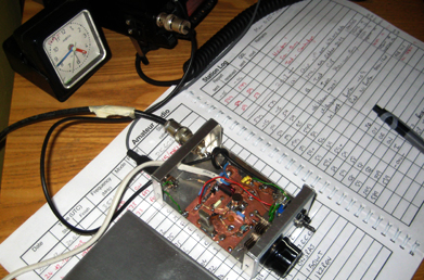
Today I started some tests at 8.97kHz with my mag-mounted E-field probe (EFP) on the car roof. As usual, the transmitter was my 5W QRSS3 beacon feeding the 20m spaced earth-electrode antenna in the garden.
The logical starting point was to drive to my usual "strong" test site 1.6km from home and compare signal levels on the usual 80cm square RX loop with that on the EFP. For reasons I have yet to understand the signal was NOT copied, even on the loop! What I did see was what looked like an FSK telemetry signal, possibly from overhead power lines close to 8.97kHz. I've never seen this before. Anyone know what it is?
I then drove to my new QTH (due to be occupied in about 4-5 months time) which is 0.4km from the TX and sat in the car in the drive with the iPod Touch 4g running SpectrumView software connected to the EFP. The antenna was a short 19 inch whip. Signals were copied quite well (see photo showing "3" from my callsign). The bandwidth on SpectrumView cannot be narrowed enough to optimally receive QRSS3 and results would be better with the PC set to 0.34Hz bandwidth.
Tomorrow I'll have to find out why I couldn't see my earth-mode signal at the usual test site on either antenna. I'm also going to do some /M reception at 8.97kHz using the E-field probe and laptop with Spectran set to 0.34Hz or 0.17Hz bandwidth. With a continuous signal I'll be able to log the signal level as I drive around the village and nearby.
The logical starting point was to drive to my usual "strong" test site 1.6km from home and compare signal levels on the usual 80cm square RX loop with that on the EFP. For reasons I have yet to understand the signal was NOT copied, even on the loop! What I did see was what looked like an FSK telemetry signal, possibly from overhead power lines close to 8.97kHz. I've never seen this before. Anyone know what it is?
 |
| 8.97kHz 5W earth-mode signal at 0.4km on E-field probe |
Tomorrow I'll have to find out why I couldn't see my earth-mode signal at the usual test site on either antenna. I'm also going to do some /M reception at 8.97kHz using the E-field probe and laptop with Spectran set to 0.34Hz or 0.17Hz bandwidth. With a continuous signal I'll be able to log the signal level as I drive around the village and nearby.
27 Feb 2013
What IS amateur radio?
This is a question I keep asking myself. It clearly means different things to different people, but I am saddened by the trend to cheque book amateur radio.
In its early days the hobby was clearly about experimental radio: making receivers and transmitters that communicated over short distances, with many/most of the parts being hand-made, even down to the variable "condensers". Over the years this has changed for many (most?) amateurs and now one could be forgiven for thinking all that matters is how expensive ones new HF radio or antenna is, so one can boast about how wonderful ones station is to others on HF.
I was struck by the cost of the hobby, for some, again tonight when visiting http://www.bigskyspaces.com/w7gj/vhf.htm and looking at the massive and very expensive antenna farm at W7GI. Now this 144MHz antenna, like many, antenna arrays at this amateur's QTH is aimed at reliable EME operation where large antenna gains help. But what I see is 16 very expensive antennas plus an equally expensive support structure, expensive coax and an expensive mast. This is just one antenna for one band. He has another very big array for 50MHz too, plus no doubt a shack full of expensive radios and linears. The rotator to turn this lot will be a very large device indeed. Yes, successful EME operation needs big antennas and high power, but honestly is this AMATEUR radio still or semi-commercial experimentation?
I can understand why an amateur may want one 100W commercial radio as the "mainstay" radio for the shack, but I see many shacks loaded to the gunnels with very expensive radios that must have cost their owners well over £10k and in some cases well over £20k. It amazes me how much money some amateurs must invest in their hobby. I had a decent job and a decent salary when I worked, but there is no way I, personally, could justify this sort of expense on my hobby. It's a personal view and I do not want to preach to others on how to enjoy their hobby, but I am fascinated that spending lots of money on radios seems to be the norm.
Are any readers prepared to share (in the comments) how much they spend, on average, a year on their hobby? £10, £100, £1000, £10k, £20k? Just for the record, I reckon on about £2 a week (a couple of new HF transceivers over 12 years plus the odd accessory and components). It is possible to really enjoy the hobby and spend less than the cost of a coffee every week.
My question is, what IS amateur radio?
472kHz earth-electrode WSPRing this evening
The 472kHz WSPR beacon has been running this evening using the 20m spaced earth electrode antenna described in my March 2013 RadCom article. A reminder that there is NOTHING in the air at all, just the wires along the grass to the earth rods.
Quite a few reports received and given already.
The same earth electrode antenna will be used at the TX end of my VLF test with the mag-mount E-field probe RX tomorrow morning.
Quite a few reports received and given already.
 |
| 472kHz unique WSPR reports received so far tonight |
Stake out on 481THz
 |
| 481THz RX on tripod with optics. |
Yesterday it was so gloomy that I could hardly work out where to aim, so this now means I can be within a few degrees accuracy on initial set-up. I've also adjusted the aim of the TX beacon optics. Visibility for Thursday night is forecast to be "very good" with cloud cover according to my Met Office app, so let's hope it works OK tomorrow.
The RX and 100mm optics are shown above. Note that the upper tripod extension (below the tilt arm) is rarely extended as the whole thing is then too wobbly. I need a more sturdy tripod. Also, the low cost gunsight scope (bought for just a few pounds off eBay) is of little use at night (too little light) but very useful in daylight.
Mag-mount E-field probe on 8.97kHz
Just as an experiment, this afternoon I modified my mag-mounted FET drain tuned E-field probe to work on 8.97kHz. The last time I rigged an E-field probe on 8.97kHz and went looking for my earth-mode signal results were very disappointing wih just a couple of places within 2km radius where the 5W beacon was copied, but tomorrow morning I'll see how well (or not) it works. To tune the FET drain to 8.97kHz I just substituted the 137kHz tuned circuit with an 83mH Toko potted coil in parallel with 4n7. Tuning is reasonably sharp. Whether the car grounding will make a big difference we'll see in the morning.
26 Feb 2013
Eddystone User Group

In my case I owned a Mk 1 EC10 receiver similar to the one shown here. This was state of the art in the late 1960s when it sold for £48. By modern standards it is a pretty rubbish receiver.
481THz over the horizon test: no success tonight
Weather this evening was not suitable for the tests, although I did try. I set up the QRSS3 beacon pointing out of my bedroom window using the local windmill as the aiming point. This is on the top of our small hill which rises about 15m. I then drove to a spot 3.6km away over the hill to look for the signal with my sensitive RX and 100mm optics using Spectran to display the trace. Unfortunately this time the slight drizzle and murk was just too bad and no signal was copied, although I've had good results in the past at a very similar spot.
 In daylight I need to recheck my beam alignment at the RX location as it was sufficiently murky to not see the local landmarks used to help aim the RX last time. Despite panning across 45 degrees of aim nothing at all was copied of my signal. I shall repeat the test in better optical conditions.
For those interested, the 1W 10mm diodes are available from http://www.ebay.co.uk/itm/350347623711. You get 10 pieces for £9.26 with free postage and they are very BRIGHT.
For those interested, the 1W 10mm diodes are available from http://www.ebay.co.uk/itm/350347623711. You get 10 pieces for £9.26 with free postage and they are very BRIGHT.
481THz optical tests over the horizon tonight
This evening I am doing my first "over-the-horizon" optical test this year. The main aim is to check performance with the new receiver and to see how I get on using the iPod Touch 4g running SpectrumView software as the way of seeing the QRSS3 signal. I shall also be taking the laptop running Argo or Spectran.
The receiver circuit is the one in Practical Wireless this month by Stuart Wisher G8CYW. This is simple but works well in darkness. I've added an interface to the iPod Touch 4g (a capacitor and a resistor needed to enable the external mic input) and changed the coupling caps and op-amp gain. Using just MPF102 and 2N3904 devices the results look good. The low noise op-amp may be overkill unless one uses super low noise FET and transistor stages too.
After the tests I'll post results in the blog.
 | |
| Latest receiver that seems more sensitive than my older RX |
After the tests I'll post results in the blog.
40m WSPR with 50mW - best DX spot 6505km
 |
| Reports received with 50mW on 40m |
25 Feb 2013
Bug keys
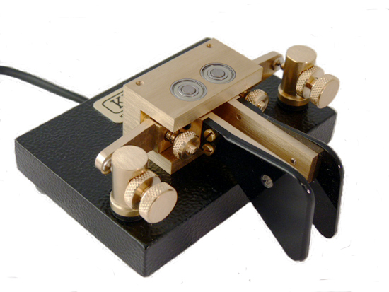 |
| Kent twin paddle key |
Some years ago I bought a beautifully made Kent paddle key but I've hardly ever used it because I kept making mistakes. So, today I dug it out and decided to persevere with it on 40m CW. I managed a nice (unexpected) 2-way QRP QSO with Rick DK4QK who, despite my sending, managed to copy everything. Later I worked DM0E on 2-way QRP as well, using the bug. Like all things, good CW comes with practice and use. Using a paddle key should allow me to send better and faster CW with a little bit more practice on my part.
So, if you hear me calling CQ on 40, 20 or 10m in the coming days on CW, and there are plenty of mistakes and extra dots, then you'll know who it is.
20m WSPR
As the weather is totally miserable I decided to sit by the fire today instead of doing any amateur radio building. In the comfort of the lounge I am watching the spots being sent and received with 2W to the Par 10/20/40 end-fed antenna on 20m WSPR. 20m is not a band I use much, preferring 10m, although conditions on 10m have nothing like matched the conditions close to past sunspot maxima.
 |
| Some decent range spots (TX and RX) despite lackluster conditions on 20m |
Exchange rate changes and ham rigs
In recent weeks the pound sterling has declined quite a bit against the US dollar and the euro. Against the dollar it has fallen from around 1.62 dollars to the pound to around 1.51 to the pound. This makes purchases of rigs like the KX3 even more expensive here in the UK.
On the other hand, the yen has weakened from 125 to the pound to around 142 to the pound. Expect some discounting of Japanese rigs in the UK incoming months. The latest yen exchange rate suggests a new FT817ND should be less than £500 again soon.
Which major dealer will be really public spirited and pass on their savings to us the amateur radio public? Martin Lynch or Waters and Stanton?
24 Feb 2013
A PSK31 QSO
Well, the little grandchildren have gone back home to mum and dad so the house is very quiet (and tidy!) again. This afternoon I decided to do a bit of QRP on 20m as a change. First a nice 2-way QRP QSO with Emi IZ4RDX who was running 5W (me 2.5W) and then a PSK31 QSO with Luis EA3UV. Neither contacts were great DX, but fun. For the PSK31 QSO I decided NOT to use those pre-prepared messages and instead just keyed in what I wanted to say as the QSO went along. It felt like a real QSO, which was nice.
Tomorrow I hope to get back to the optical beacon work, but after 4 days of (lovely) little grandchildren this afternoon I just needed to "chill" as they say. The plan is to build a beacon TX that will allow a range of subcarriers and also continuous subcarrier transmission as well as CW and QRSS beacon messages. I hope to get out "over the horizon" looking for the signal later in the week. Watch this space - literally if you are nearby, HI.
Tomorrow I hope to get back to the optical beacon work, but after 4 days of (lovely) little grandchildren this afternoon I just needed to "chill" as they say. The plan is to build a beacon TX that will allow a range of subcarriers and also continuous subcarrier transmission as well as CW and QRSS beacon messages. I hope to get out "over the horizon" looking for the signal later in the week. Watch this space - literally if you are nearby, HI.
22 Feb 2013
PSK31 mode
Julian G4ILO mentions his enjoyment of PSK31 on HF on his blog today. Although I've had a fair few QSOs and some good DX with this mode over the years, I'm not a great fan of it.
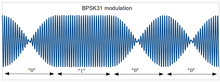 Although Julian rightly says it is a very good mode that well complements CW and SSB, and it is certainly true that the PSK31 part of the bands are often busy when CW and SSB signals are absent, to me QSOs feel too formalised with exchanges that follow fairly standard formulae. Too often it feels like a PC talking to a PC. Maybe I should try next time to avoid using these pre-programmed messages and go for a normal free-form keyboard "chat" instead.
It's a while since I've tried PSK31 on HF. Maybe next week when the grandchildren go home I'll give it another go.
The ARRL reports that Varicode, as used in PSK31, has now been officially recognised by the ITU. See http://www.arrl.org/news/amateur-created-varicode-adopted-as-itu-recommendation .
It's a while since I've tried PSK31 on HF. Maybe next week when the grandchildren go home I'll give it another go.
The ARRL reports that Varicode, as used in PSK31, has now been officially recognised by the ITU. See http://www.arrl.org/news/amateur-created-varicode-adopted-as-itu-recommendation .
More VLF activity from Germany
DJ8WX has been experimenting with a new GPS locked frequency source and is trying to put a signal out on 8.9700000kHz. The signal has been received strongly by several stations including Paul Nicholson in Todmorden and at PA1SDB. This is the signal at PA1SDB over the last few days. Note the timescale on Peter's grabber covers several DAYS. Such is the world of amateur VLF!
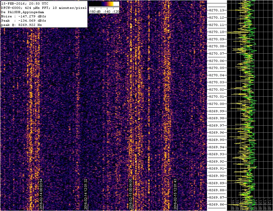 |
Signal from DJ8WX now on 8.970000kHz (was 8.970022kHz)
|
19 Feb 2013
Nanowave over the horizon tests - nearly ready
| Original optical beacon |
| Optical beacon capable of continuous subcarrier (choice of freqs) or QRSS/CW |
 |
| SpectrumView in action - it's brilliant |
I also want to optimise the use of the iPod Touch 4g as a handheld audio spectrum analyser. I have used it for this sort of test before using an excellent package available free called SpectrumView (see screenshot) available from Oxford Wave Research. With a laptop PC, running Spectran, the problem is the brightness of the screen which emits an interfering optical signal. With a tiny iPod Touch it is much less bright and can be held in the hand. Unfortunately the bandwidth can't be screwed down as narrow as with Spectran on the PC, so there will be S/N limitations. One test will be to see how far away I can detect my beacon (about 0.5W into the LED) over the horizon using just the optical receiver and the iPod Touch.
The beauty of 481THz (red light) work is the kit is simple: everything that matters is at audio frequencies and can be built and tested with the simplest of test gear.
18 Feb 2013
Trio TR2300 1W 2m FM portable

I had it to get on 2m FM from home mainly. A small vertical dipole was erected at gutter height and with this set-up I could work well equipped stations out to around 50-60 miles. It was actually a rather good little radio that also got used in the car on holiday in France with my French call F0HXF.
Why it was sold I cannot remember. Of course, these days you get all the functionality, and a lot more, in a tiny handheld like the VX3 and the FT817 produces more than 6dB more power on all bands and modes from 160m-70cm in a box about 30% smaller.
Incidentally with 2 days to go there have already been 31 bids, so someone must want one.
ARRL DX CW contest
Until I read about it on G4ILO's blog, I'd quite forgotten about this big contest. Rather late on Sunday afternoon and evening I decided to have a go and see what could be worked on 40 and 20m. Although I managed a few US contacts with the 2.5W QRP I do find CW contests hard work: people send SO fast and by the time I've called with my straight key they've usually already had another QSO. I suspect many these days use keyboards and auto keyers most of the time in contests. Actually I quite enjoy the odd SSB contest as I can talk (nearly) as fast as anyone else. Even with 2.5W SSB it is surprisingly easy to make contacts in a big contest, especially late in contests when the big guns are looking for new stations to work. Overall, I prefer experimentation, but a contest just for fun can be quite cathartic.
16 Feb 2013
New 481THz receiver working well
 |
| Optical RX in small screened box attached to a 110mm drain pipe "stopper" |
Build method is my usual copper clad board with MeSquare pads built dead bug style. The junction of the SFH213 cathode and the gate of the FET must be kept well above the ground though to reduce losses.
To test the set up I modulate a small red LED mounted on the ceiling of my building shack with a 1kHz tone. With all lights out and in near total darkness I compare the level on the audio generator that I can just hear with that of my reference optical receiver. Both the new unit and the test unit are on the bench about 1.5m away from the (just glowing) LED. If the system is working well the S/N is good with the LED barely visible by eye. There are quantitative ways of measuring the sensitivity using Spectran on a PC but this means having the PC out of the room as the display would otherwise desense the RX!
I have yet to test this when mounted in the 110mm drain pipe with 100mm lens. This gives an antenna gain of around 24-30dB. A good test will be the GB3CAM optical beacon which I can just detect with my older head at a distance of around 32km.
HF noise and 481THz experiments again
This morning I notice that most of HF, to 15m at least, has an S6 noise level here. it is making operating on HF a real pain.
Actually I am beginning to think about restarting the 481THz (red light beam) over-the-horizon QRSS tests again. At least at nanowaves you can see the interference! My first project will be to build a new nanowave receiver using the SFH203 detector which should be some 6-7dB more sensitive than my current detector head, which is already impressively sensitive. Next I want to try out the QRO Phlatlight LEDs I've had for several months but not yet fired up. They should be VERY bright with 100mm lenses, so a lot of care will be needed.
Practical Wireless is currently running a series of articles on lightwave communications written by Stuart G8CYW. This should be an ideal introduction for anyone wanting to have a go at speech over light or long range data transmission (line of sight or non line of sight). Stuart has done more than anyone to encourage light beam communications.
 |
| Phlatlight QRO LED for 481THz over-the-horizon QRSS tests |
Practical Wireless is currently running a series of articles on lightwave communications written by Stuart G8CYW. This should be an ideal introduction for anyone wanting to have a go at speech over light or long range data transmission (line of sight or non line of sight). Stuart has done more than anyone to encourage light beam communications.
G3XBM website
Please let me have feedback on how you find my new website layout for my main website at www.g3xbm.co.uk . In recent weeks there's been a complete overhaul of the site but I have yet to get any feedback from people who visit it, good or bad.

Please email me at address given on the website and above, or leave a comment here. To prevent spam bots you will have to copy the address into your email package manually as the address is shown as a jpg image, not a clickable link.
Finally may I apologise for the silly nonesense you have to go through to post a comment here on this blog. When I remove the web bot filter ("copy the words you see" stuff) I get loads of rubbish, so felt it was necessary to keep it, despite the hassle. Alternatively you can send me any blog comments by email and I will add them for you.
15 Feb 2013
G3XBM online grabber
This evening I've been setting up my on-line grabber again so that I can monitor VLF, LF or MF activity and upload what I am receiving to the internet for others to see. The grabber is, at this stage, only on intermittently as I experiment. The plan is to have a dedicated VLF or LF receiver and PC for this purpose, so the grabber can be run almost 24/7.
The main weak signal detection is done using Argo software running on my PC connected from my RX via the SignaLink USB interface. The captured signal is then uploaded to a location in my public Dropbox which is then linked to from my webpage. So, what appears on the G3XBM online grabber page is what I am seeing with Argo. The direct link to the Dropbox image is http://dl.dropbox.com/u/15047843/g3xbm.gif .
The main weak signal detection is done using Argo software running on my PC connected from my RX via the SignaLink USB interface. The captured signal is then uploaded to a location in my public Dropbox which is then linked to from my webpage. So, what appears on the G3XBM online grabber page is what I am seeing with Argo. The direct link to the Dropbox image is http://dl.dropbox.com/u/15047843/g3xbm.gif .
 |
| G3XBM online grabber |
OXO on 14MHz
 |
| An OXO transmitter on 14MHz |
It works fine with reverse beacon reports from Iceland and Slovenia and a nice 2-way QRP QSO with IK2RGV who was running 5W.
The OXO really is a classic circuit: you just build it and it works. Another version is on the QRPkits page.
FT817 v KX3 (part 2)
Thanks for all the many comments both here an in private emails. Basically I am looking for a good second QRP transceiver to work along side my existing 12 year old FT817 that continues to work perfectly. There are times when I'd like to WSPR on one band whilst operate CW or SSB on another. Also, the second transceiver allows me general coverage RX whilst TXing on the first unit. Since I sold my IC703 to a friend the year before last, this has not been possible.
At the moment, I am still inclined to buy an FT817ND rather than the KX3. As YO9IRF said in the earlier post and on his blog, the FT817 is close to the ideal for a portable QRP radio, even after 12 years. Although it does not match the RX performance of the KX3, it does perform remarkably well, and of course it also covers the 144 and 432MHz bands and with all modes. And it is half the price.
At the moment, I am still inclined to buy an FT817ND rather than the KX3. As YO9IRF said in the earlier post and on his blog, the FT817 is close to the ideal for a portable QRP radio, even after 12 years. Although it does not match the RX performance of the KX3, it does perform remarkably well, and of course it also covers the 144 and 432MHz bands and with all modes. And it is half the price.
14 Feb 2013
Email habits
As someone who gets around 50-60emails a day, sometimes more, even though I am supposed to be retired, the link below offers us all some good sound advice on how to manage emails well. A good half of the emails I get are about projects on this blog or my main websites, so it's my own fault, HI.
My PC or iPod Touch tend to be on for a lot of the day and am almost addicted to reading the emails. Usually I reply promptly but occasionally emails get filed waya having forgotten to reply, for which I make a general apology.
Anyway, here is that link: http://zenhabits.net/e/
My PC or iPod Touch tend to be on for a lot of the day and am almost addicted to reading the emails. Usually I reply promptly but occasionally emails get filed waya having forgotten to reply, for which I make a general apology.
Anyway, here is that link: http://zenhabits.net/e/
13 Feb 2013
FT817 v KX3
People who own the Elecraft KX3 generally rate it very highly as it is a very feature rich product with an excellent receiver. However to buy one with all the features such as the auto ATU and the internal battery box is EXPENSIVE. For the price of one fully loaded KX3 one could buy 2 well proven FT817ND transceivers.
One has to question whether the KX3 truly is worth the extra cost. Although a trail friendly radio, the KX3 does have a messy cabling interface with wires everywhere, it would appear, from both sides! By contrast, the FT817 has simple, clean interfaces and is as happy in the field, in your hands or on a desktop. The KX3 looks functional, but hardly a thing if beauty.
I'd be interested to hear the views if others.
This video, by Jim Mullen, is the first part of 2 that compare the RX of the KX3 and FT817.
10 Feb 2013
8.97kHz VLF amateur activity
 |
| DJ8WX's VLF signal received by G3ZJO (frequency is Hz) |
Pedestrian Portable HF DXing
 |
| G3XBM operating pedestrian portable in South Devon |
Nice blog site with useful info
 |
| A nice Pixie transceiver and tuner on the PD7MAA blogsite |
Simple antenna current meter
 |
| https://sites.google.com/site/arvidevans/LED_Antenna_Current_Indicator.png |
Simple pleasures
Today for a change, and whilst waiting for the family and grandchildren to arrive for half term holiday, I simply went on 20 and 15m and just operated using the 2.5W pep SSB from the FT817. No great DX, with the best contact being OY, but a few nice enjoyable contacts in the log. The speech processor certainly helps.
It is tempting now to build a multi-band VXO controlled QRP CW transmitter to use with the FT817 (on receive) as it is a while since I operated QRP CW on 40 and 20m. With the EF-10/20/40 antenna now up it is an ideal time to do this and enjoy the simple pleasures of operating QRP on the HF bands again. In my mind I think a 2N3904 VXO and buffer followed by an IRF510 PA at around 2-3W.
It is tempting now to build a multi-band VXO controlled QRP CW transmitter to use with the FT817 (on receive) as it is a while since I operated QRP CW on 40 and 20m. With the EF-10/20/40 antenna now up it is an ideal time to do this and enjoy the simple pleasures of operating QRP on the HF bands again. In my mind I think a 2N3904 VXO and buffer followed by an IRF510 PA at around 2-3W.
9 Feb 2013
Par EF-10/20/40 Antenna and a comparison
This afternoon I decided to take down my 10m halo for a while and replace it with a lower antenna: the LNR Precision (was Par) EF-10/20/40 end fed wire antenna, which I've owned for some years but not used recently. As it suggests, it covers 10, 20 and 40m with a very low SWR, although it is a reasonable match on several other HF bands too.
See http://www.hamradio.me/antennas/lnr-precision-ef-102040mkii-test-data.html for an analysis of this antenna. The antenna works very well and on 40 and 20m WSPR I was getting plenty of spots with 500mW to 5W.
On 40m I did a comparison between the horizontal EF antenna and the earth-electrode antenna. A series of transmissions was made with each antenna in turn, then I compared WSPR spot S/N received from a number of stations.
The conclusion is the earth-electrode antenna is around 9-16dB down on the EF antenna on 40m, so averaging about 2.5 S-points down. The test is not too accurate as conditions change, the earth-electrode and EF have some directivity and the reports sample size was small.
See http://www.hamradio.me/antennas/lnr-precision-ef-102040mkii-test-data.html for an analysis of this antenna. The antenna works very well and on 40 and 20m WSPR I was getting plenty of spots with 500mW to 5W.
 |
| Photo on http://www.hamradio.me website of the Par antenna |
The conclusion is the earth-electrode antenna is around 9-16dB down on the EF antenna on 40m, so averaging about 2.5 S-points down. The test is not too accurate as conditions change, the earth-electrode and EF have some directivity and the reports sample size was small.
8 Feb 2013
Grandchildren time and new projects
We've all 4 grandchildren coming to stay at different times over the next couple of weeks. As usual, this means that amateur radio activity will decrease somewhat as the upstairs shack gets used as a real bedroom again. It will still be possible to run WSPR on LF and MF and some of the HF bands from time-to-time, but not in the evenings.
Whilst this "interlude" is going on, it will be a good time to take stock and think of the next projects. The early part of 2013 has seen a burst of activity related to the earth-electrode antenna and the ferrite rod TX antenna, neither of which was planned. I also did some more work on a 136kHz transverter Several projects, including the 136kHz transverter, are still unfinished:
Tenbox 10m AM transceiver
Although most of this has been breadboarded and is working, it still has to be boxed and properly documented. I quite fancy a PCB for this simple design and that needs to be created.
471THz over-the-horizon tests
My PhlatLED very high power LEDs have yet to be switched on and I still have to build a more sensitive detector.
De-cluttering and Test equipment
With a move to a new QTH later this summer I really ought to think about de-cluttering and sell some lesser-used radio equipment. At the same time I could do with building some more pieces of simple test equipment such as a proper QRP power meter, a resistive SWR bridge, a better ATU, and a very basic spectrum analyser.
Other projects
There is a list as long as my arm of other projects I'd like to tackle, but it takes me all my time to do the ones I do!
IC7100 Sneak Preview Video
There is a short YouTube video clip from ICOM America describing the IC7100 with a look at the various connections on the head and main unit. The thing that impressed me was just how small this transceiver is. It looked larger in the earlier pictures. The IC7100 is likely to be on sale in the UK in late spring at around £1700-1800 without the D-star option. Not cheap, but a lot of radio.
The specification of the IC7100 is available here.
7 Feb 2013
Hard to believe this is without a conventional antenna
As 40m went rather quiet, I QSYed to 80m WSPR on the earth-electrode antenna this evening. The log below is from just one single 2 minute transmission with 2W.
 |
| 12 spots in one 2min burst this evening with 20m spaced earth-electrode antenna |
Earth-electrode antenna on 40m
This evening I have been trying my stealth antenna (20m separated earth-electrodes, wire in the grass!) on 40m again and getting plenty of WSPR spots. I did try to match it on 160m earlier but couldn't get it below about 3:1 using the Elecraft T1 auto-ATU. Spots from 6 countries in an hour (LA, DL, F, EI, GM, G) with strongest reports from Cornwall (-3dB S/N) which is in the line of the wires/loop.
Earlier today I had a visit from Ted G4NUA, so I showed him my 137kHz antenna, "Where is it?" he said. Exactly - the wire runs back to the house from the far earth rod IN the grass and it is all but invisible!
 | |
| WSPR spots received using 20m spaced earth-electrode antenna with NOTHING in the air. |
6 Feb 2013
Earth-electrode antenna on 80m
This evening I have been using the 20m baseline earth-electrode antenna on 80m. From the shack (upstairs) there is a 20m coax down to the back of the garage where it picks up the earth electrode wires. On 160m the match is poor but on 80m a near perfect 1:1 match, so no radiation from the coax.
 On receive there are plenty of signals visible and decoding on WSPR and on TX it seems to be getting out pretty well with 1W RF from the FT817. I am not sure of the ERP on 80m, certainly higher than on 630m (472kHz), but it does appear to be quite effective.
 Tomorrow evening I'll match the earth-electrode antenna with the Elecraft T1 auto-ATU and see how it performs on 160m. I'll put the ATU right at the earth-electrode end of the coax so that we'll see the radiation from the earth-electrodes and not the feeder.


10m WSPR
 |
| 10m WSPR reports late this afternoon |
137kHz E-field probe on my website

The whole unit is fixed to a car mag-mount antenna and works very well indeed.
5 Feb 2013
OFCOM licence exempt loopholes
Still trying to see if there are any loopholes that would allow me to legally carry out radiated tests between 40-80kHz as mentioned in earlier posts.
Currently I'm pondering an OFCOM document called IR 2030 - UK Interface Requirements 2030 Licence Exempt Short Range Devices . This document seems to offer some hope by adopting the licence exemptions applicable to short range devices such as metal detectors and induction communications systems. For example, for metal detectors, it says,
"That part of an induction system designed or adapted to produce:- (a) a controlled magnetic field; and (b) a predetermined recognisable signal when operating within that magnetic field"
in the frequency range 9 - 148.5 kHz the emission level is [not greater than] 70 dBμA/m at 6 m. My maths is not good, but this is 3.15mA/m which sounds quite a lot. Some other specifications allow 72dBuA/m at 10m, which is considerably more. It seems I need to read a copy of document EN 300 330-2 which describes the rules and test methods. Although these rules are designed for systems that use induction field communications, the unknown is how much signal that meets these requirements might be radiated and detectable with sensitive kit in the far field?
Incidentally, it is surprising how many non-amateur frequencies can be used legally with (useful) QRPp power levels in the MF, HF, VHF range, no doubt with some type approval stipulation or at least CE declarations being required on the equipment. With WSPR or similar weak signal modulation systems, some most interesting experiments could be carried out in unusual parts of the LF, MF, HF and VHF spectrum, apparently without a licence being needed, as long as the emissions limits are met.
OFCOM ..."no you can't" again at LF
This afternoon I got another email from OFCOM. Although my requests have been passed upwards for other more empowered people to consider, it is effectively a refusal of permission to carry out experimental research for short periods even at 10uW EIRP on clear spot frequencies in the LF spectrum between 40 and 80kHz without getting a £50 Non Operational (T&D) Licence, which I am not prepared to do.
Thank you Mark VK6WV
Amateur radio has some very kind and generous people still.
In the post today I received a letter from Australia quite unexpectedly. In it were a number of 480kHz ceramic resonators that Mark VK6WV had sent me, as a gift, for me to try in a 472kHz transmitter. Mark, many thanks! This was a very nice surprise in the best spirit of amateur radio. I shall indeed use these to build a little 472kHz tunable CW transmitter. I'll also try using these in an RF stage of a receiver for the 472kHz band.
This is not the first time I have been on the receiving end of generous fellow amateurs and it is so lovely to know that there are kind people about who simply want to give and to share. Mark didn't even give me an email address that I could use to thank him, so I am doing so here via the blog.
Wonderful! You made my day Mark.
137kHz 30-40W TX transverter schematic
As promised, here is the schematic of the current 30-40W TX transverter for 137kHz. I have used a 10MHz crystal but a lower local oscillator frequency would be slightly better from a stability viewpoint when using narrowband modes like QRSS30 or WSP15. One choice is to use a low cost 1.843kHz crystal mixing with the driver transmitter's output at 1.979kHz. When a stable external LO source is possible e.g. a GPS disciplined oscillator, remove C7 and feed the LO into the double balanced mixer. Although an SBL-1 mixer was used an alternative, available from eBay is the ADE-1. As balance is not super critical, a home made double balanced mixer would also be possible.

For PA heatsink I just used a couple of small TO220 heatsinks in the prototype. With optimal PA matching into 50 ohms there is little heat from the PA device. A larger heatsink could prevent overheating when the antenna is mismatched. My output network was optimised for my slightly higher than 50 ohms output load presented by my earth electrode antenna.
ERP is around 30uW with my earth-electrode antenna.
Some may prefer to use capacitive coupling into the FET gate. If TR3 failed open circuit, the gate voltage would rise leading to the IRF640 failing. Hasn't been a problem so far though.

ERP is around 30uW with my earth-electrode antenna.
Some may prefer to use capacitive coupling into the FET gate. If TR3 failed open circuit, the gate voltage would rise leading to the IRF640 failing. Hasn't been a problem so far though.
4 Feb 2013
A dialogue with OFCOM
At last, and only 3 months late, OFCOM have renewed my NoV for 8.7-9.1kHz VLF operation.
Currently I am "in negotiation" with OFCOM on another matter mentioned a few days ago.
In the next few months I want to do some QRPp radiated tests with the earth-electrode antennas at some frequencies between 9kHz and 137kHz. Ideally this would be around 35-45kHz and 70-80kHz, where I can find a quiet spot without any activity from primary users like the Ministry of Defence. With QRSS, continuous carrier or WSPR and with an EIRP of around 10uW it should be interesting. Tests on 137kHz suggest this power is enough to see a radiated signal out to at least 25km locally with an E-field probe on the car, which would allow me to check coverage and polar plot. On the lower frequencies this may be limited to just 5-10km, but that would be OK.
But, OFCOM say they will not grant me licence-exempt permission to operate in this part of the spectrum, even at the miniscule powers and bandwidth (uWs and a few Hz).
They say they would HAVE to consult with the primary users and this would take months. They suggest instead I apply for a Non Operational (Test and Development) Licence, but does that not need primary user approval too? Problem is this licence costs £50 a year, which sounds like total overkill when the risk of me interfering with anyone is about as likely as me winning the lottery or landing on the moon when I jump.
Now, I could just go ahead and do the tests anyway knowing I will not cause anyone a problem. Really this is not the way it should be and anyway I'd like to publish the results later. Hardly possible if I don't do things with OFCOM's approval. I am hoping that the good people at OFCOM will see that this is worthwhile amateur research, it won't cause ANY issues and they will soon say, "go ahead on the strict understanding that if you cause any harmful interference to primary users you close down immediately, but at that power, no licence needed." I have written back to OFCOM again this evening making this case and we'll what transpires. I also suggested issuing me a one-off NoV, but they say they won't!
Many of you will be saying, "why not just do it". If the powers that be really cannot see sense, then maybe I may have no other option.
Website working again
The main www.g3xbm.co.uk website is now working properly. I contacted my domain providers last night who confirmed they'd updated some systems that screwed up web forwarding. If you spot any more problems, typos or link errors please let me know.
Currently I am drawing out the schematic of my 30W 137kHz TX transverter. This should be on the website tomorrow. Still deciding whether to box it, and add the RX preamp section, or stop at this stage.
Currently I am drawing out the schematic of my 30W 137kHz TX transverter. This should be on the website tomorrow. Still deciding whether to box it, and add the RX preamp section, or stop at this stage.
Simple low cost test equipment
There was an interesting post in the last day on the GQRP Yahoo group asking about portable workbenches that led on to talk about test equipment. This got me thinking about simple pieces of test equipment and what one needs to do basic QRP design work.
In my own case the most useful pieces of kit are (1) a signal generator, (2) an inductance/capacitance meter, (3) an oscilloscope,(4) a basic power meter, (5) a wide coverage all mode RX, (6) a multimeter. I keep thinking about building a dead basic spectrum analyser too. Test probes too of course. Also a good lot of cables with BNC plugs one end and croc clips on the other.
Just wondering what other people use? Certainly for HF QRP work only very basic test gear is needed, which is why I enjoy it so much.
In a way it is a little surprising that no-one sells a low cost "all in one" test box for amateurs with many of the above in one unit. A bit like a CB test box?
3 Feb 2013
Not the best of weeks
Well, apart from the excitement over the ferrite rod on TX, this has not been a too brilliant week.
As you saw in the last post, my website domain name provider seems to have messed up web forwarding thereby screwing up the G3XBM website, for now at least. This is annoying as it has also caused issues on the www.cambschoral.org.uk website that I set up and maintain for the Cambridgeshire Choral Society. And then there is 137kHz where a week of trying has netted me spots from just 4 unique reporters. Even the effort to get WSPR15 working was all but scuppered by the 4Hz drift over 15 minutes in the FT817.
In the grand scheme of things none of this much matters. Perhaps next week will be more fruitful, HI. In the meantime, I'm watching TV and having a whisky!
Website woes
In the last few days I've done a major overhaul of my main website www.g3xbm.co.uk . All was working fine, but for some reason the web forwarding is not working correctly. Landing on the www.g3xbm.co.uk site you should automatically be forwarded to https://sites.google.com/site/g3xbmqrp3/ which is where the site is now located on Google Sites. So far so good, and this happens, although the address bar, which should change to the new site address based on how I've got my forwarding set up does not. Not only that, but clicking any images does NOT bring up larger, clearer images as it should although this works fine when you start with https://sites.google.com/site/g3xbmqrp3/ . So, I think it is a problem with the web forwarding, which I will try to fix.
In the meantime, you may want to go directly to https://sites.google.com/site/g3xbmqrp3/ if you want to explore the revised site.
In the meantime, you may want to go directly to https://sites.google.com/site/g3xbmqrp3/ if you want to explore the revised site.
First WSPR15 transmission decoded successfully
After a LOT of effort, G8HUH managed to decode my WSPR15 transmission on 137.607kHz at 1815 this evening. Even with a very low (1.7MHz) LO, the drift was still 4Hz in the 15 minute TX period, mainly due to the FT817 I think. At only -32dB S/N decode this was actually not as good a result as with WSPR2 over the 250km path. Short of force cooling the FT817 or using a rig with a TCXO reference, there is nothing more I can do.
My WSPR15 transmissions were also copied and decoded by G4FFC and G4FEV.
CONCLUSION: WSPR15 is a much more tricky mode to use successfully unless the transmission is very stable. This is the screenshot Tom G8HUH sent me.
My WSPR15 transmissions were also copied and decoded by G4FFC and G4FEV.
CONCLUSION: WSPR15 is a much more tricky mode to use successfully unless the transmission is very stable. This is the screenshot Tom G8HUH sent me.
 |
| 30uW ERP 137.607kHz WSPR15 signal received by G8HUH |
137.5kHz WSPR15 tests
Using a very stable external signal generator as my 10.0000MHz LO 5dBm injection, I'm now in a position to try WSPR15 with a stable signal. After a quick frequency check with WSPR2 I propose to switch to WSPR15 with its greatly improved weak signal capability for this evening and overnight. WSPR15 activity takes place in the 25Hz slot just above the WSPR2 activity.
Please let me have any reports.
The first WSPR15 transmission will occur at 1600gmt.
Update: Tom G8HUH reported an upward drift of 5Hz during the 15 minute TX burst, so I've moved the LO to 1.7000MHz and the FT817 to 1.836kHz. Drift (all due to the FT817) is now 1Hz. Awaiting decodes.
Please let me have any reports.
The first WSPR15 transmission will occur at 1600gmt.
Update: Tom G8HUH reported an upward drift of 5Hz during the 15 minute TX burst, so I've moved the LO to 1.7000MHz and the FT817 to 1.836kHz. Drift (all due to the FT817) is now 1Hz. Awaiting decodes.
137.5kHz ...it's getting repetitive
Well, I've had the 137.5kHz WSPR2 beacon running for about 18 hours now, almost continuously on a 25% TX cycle. I've tried to drum up reporters by posting on the WSPRnet chat page, RSGB LF Yahoo Group and the LF Blacksheep reflector, plus a few direct emails to stations likely to copy my signal.
All I've managed are the very consistent reports from good old G8HUH at 250km. The signal is obviously spanning this distance without any issues so why no others reporting?
Later I am going to replace the 10MHz LO in my transverter with the stable source from my synthesised signal generator and have a go tonight at WSPR15 (15 minutes TX periods) and see if that gets me a few more reports. It should be several dB more sensitive. If that fails to get anywhere, then I am calling it a day on 137kHz. In terms of returns for effort, this is not good value.
 |
| Consistent 137.5kHz WSPR spots from G8HUH at 250km, but no others! |
Later I am going to replace the 10MHz LO in my transverter with the stable source from my synthesised signal generator and have a go tonight at WSPR15 (15 minutes TX periods) and see if that gets me a few more reports. It should be several dB more sensitive. If that fails to get anywhere, then I am calling it a day on 137kHz. In terms of returns for effort, this is not good value.
Internet Time Servers
For WSPR, and probably quite a few other programmes, it is important to have your PC's clock accurate to within a second or so. With WSPR, if you are more than a few seconds out the software will be unable to correctly decode signals. There are several internet time servers around which sync the PC clock to very accurate time standards around the word.
The one I use is http://www.worldtimeserver.
The one I use is http://www.worldtimeserver.
2 Feb 2013
Going QRT on 137kHz
Another evening on 137.5kHz WSPR and reports again from G8HUH at 250km, BUT FROM NO-ONE ELSE. I really don't want to run higher power or erect a big antenna. To be honest it is not worth the effort continuing on this mode on this band as there are too few monitoring stations. At the moment I am not inclined to box and finish the transverter. Instead, I think I'll try something else. Not sure what but the potential and unfinished project list is huge.
Ferrite Rod TX on 10MHz WSPR
This morning I tried the ferrite rod antenna on 10MHz WSPR TX for an hour. As before, I mounted the ferrite rod VERTICALLY on the wooden desk with all other antennas disconnected - the only other antennas are a VHF colinear and a 10m halo, and both of these are around 10m away from the shack. Quite a respectable number of spots we obtained with 2.5W from the FT817.
 So far I have not managed to get the ferrite rod antenna to match on 14MHz. It may be the losses in the ferrite are starting to impact performance?
I am still unclear how this tiny TX antenna is working: the assumption is a combination of a small amount of radiation off the H-field (ferrite rod coil) loop and some E-field radiation off the coiled vertical section above the tuned part. Then there is still the possibility that it is just acting as an efficient coupler into the house wiring that is doing the real radiation. Whatever, it puts a signal around Europe and occupies a volume with the tuning cap of just 15cm x 10cm x 5cm on the wooden shack table.

I am still unclear how this tiny TX antenna is working: the assumption is a combination of a small amount of radiation off the H-field (ferrite rod coil) loop and some E-field radiation off the coiled vertical section above the tuned part. Then there is still the possibility that it is just acting as an efficient coupler into the house wiring that is doing the real radiation. Whatever, it puts a signal around Europe and occupies a volume with the tuning cap of just 15cm x 10cm x 5cm on the wooden shack table.
1 Feb 2013
More Ferrite Rod TX experiments
 |
| Vertical orientation today - good results on 40m WSPR TX |

 |
| WSPR spots with the antenna above on 40m today |
When the weather is better I will take the whole kit into the back garden well away from the house and repeat. If it is working without coupling into the house wires (as I think is the case) then results should be comparable. If spots disappear then it will have turned out to be a very good random wire coupler, HI.
Subscribe to:
Posts (Atom)


