31 Jan 2013
73 Magazine back-issues on-line
http://mikeyancey.com/73mag/listauthor.php? is a searchable list of articles from the old 73 Magazine. I was pointed to it by Leon Heller for an article by Richard Q Marris, G2BZQ about ferrite rod transmitting antennas. Mike Yancey's site has some other useful stuff too, so worth a more general look.
Requests to share xbmqrp website
Friends, PLEASE, bookmark my main website correctly. Don't bookmark my pages where they are actually located (Google Sites) as these may change, as they did yesterday when I did a major site update.
So to access my main website go to, and bookmark:
So to access my main website go to, and bookmark:
Dry eyes and RF?
Testing the ferrite rod antenna on TX this evening (with lots of RF within a metre of me) I'm noticing something I used to get when testing VHF RF PAs years ago in my design days: dry eyes. I assume this is an effect of RF on the body. Apart from being madder than ever (!) I cannot say RF exposure has done me any noticable harm, but wonder if others have noticed this dry eyes effect?
Although the evidence in general is not strong, there was strong correlation back in my Pye Telecom days between those working on the design of high powered HF/VHF/UHF PA devices and those fathering girls. Maybe there was some subtle damage to sperm with exposure to high RF that made girl pregnancies more likely to succeed? Co-incidence?
A lot more controlled tests are needed, but with the widespread exposure to Wi-Fi and mobile phones it won't be too long before we find out more. So far the evidence is not at all conclusive but you do wonder whether, like smoking, we'll look back in 50 years time and say, did they really all use mobile phones and Wi-fi devices?
More Ferrite Rod TX DXing
This evening I fired up the FT817 and the small 15mm diameter ferrite rod tuned with a 365pF air-spaced variable and have been spotted on WSPR even further away. This time a couple of spots from Norway, the best being LA9JO 2096km away. As someone pointed out, I may be coupling into local wiring and this might help, but the ferrite rod behaves just like a loop with good directivity and matching just as you would expect i.e. a very low impedance tap point is needed for a good match and tuning is extremely sharp. Personally I believe the radiation is all coming from the ferrite rod and nowhere else.
 |
| WSPR reports with a ferrite rod TX antenna on 40m (5W into rod) |
TXing with a ferrite rod antenna on 7MHz
Just for fun this morning I tried WSPRing on 7MHz using JUST a ferrite rod wound coil and a 365pF tuning capacitor as a tiny loop antenna sitting on the desk. All other antennas and grounds were disconnected fully. I used one of the low tap positions to find a 1:1 SWR position and put the FT817 on 2.5W (3 blobs). The rod did not get warm. The wire used is around 0.5mm enamelled copper with around 60 turns, tapped at every few turns at the cold end.
The ERP was very small, although I have not yet measured it. To my total amazement, I got an immediate -24dB S/N WSPR report from OZ7IT in Denmark at 853km. Just proves how incredible WSPR is and what a powerful tool it is for simple experiments like this.
The ERP was very small, although I have not yet measured it. To my total amazement, I got an immediate -24dB S/N WSPR report from OZ7IT in Denmark at 853km. Just proves how incredible WSPR is and what a powerful tool it is for simple experiments like this.
 |
| Ferrite rod TX antenna on 7MHz WSPR - it worked! |
30 Jan 2013
OFCOM licence exemption
Martin G8JNJ has brought to my attention a little known, to me at least, OFCOM concession that appears to allow licence exempt operation under certain conditions in many, if not all, parts of the radio spectrum for research and development purposes.
Although OFCOM will grant Non Operational Licences (these were once known as Test and Development Licences) and charge you £50 a year for the privilege (!) to test new equipment or carry out specific research, they do NOT require a licence if emissions measured at a specified distance are below certain levels (supressed radiation conditions). See http://licensing.ofcom.org.uk/binaries/spectrum/non-operational-tech-licence/ofw357nonopguide.pdf for some guidance notes on this.
My own interest is to research earth-electrode antennas in the frequency range between 8.97kHz (where I already have done some tests) and 137kHz (where I have also tested this antenna structure). Using WSPR and other weak signal techniques, quite a lot of useful work can be done with low uW EIRP levels. It would be interesting to see how such an antenna structure behaves at say, ~40kHz and 73kHz. It may just be possible to do tests at moderate ranges (in the far field) without a licence. Now wouldn't that be interesting?
Lack of WSPR2 activity on 137kHz
Having run WSPR2 now for a couple of days on 137.5kHz, I have still only received reports from 2 different stations, although I have had LOTS of their reports, suggesting my signal is consistently reaching 250km. My signal is clearly visible to at least this distance, but without people looking I cannot be sure how much further can be expected with the earth-electrode antenna and 30uW ERP.
Although I will box up the new 137kHz transverter and tick the "finished" box I am disappointed that there is not more activity. Most LF/MF people are exploring the new 472kHz band, so interest in Europe for 137kHz is not high apart from DK7FC who is putting out a massive signal that is being copied in both North and South America.
So, what next? My mind is beginning to think of my new QTH in the village, which we expect to move to in the summer. What antennas can I put up without upsetting the neighbours? What will the noise floor be like? How much better will VHF/UHF coverage be from the top of our little "hill"?
Main G3XBM website facelift
 |
| Revised G3XBM main website |
If you bookmark the site please bookmark www.g3xbm.co.uk and NOT the page it automatically redirects too. You will no longer be able to reach the old site and I do not propose to grant individual access permission to the archived old site. Already I have had several requests for access to the old pages.
29 Jan 2013
My new WSPR DX record on 137.5kHz
Having run the 137.5kHz transverter with WSPR-15 (15 minute on periods) overnight - around 30uW from the earth-electrode antenna - I wasn't too hopeful about my chances with WSPR-2 this morning. WSPR-15 failed because of the thermal drift in the 15 minute on period I think.
Anyway I put the TX on WSPR-2 on 137.5khz this morning and let it run. After a couple of hours with no success I was VERY pleased to see I had been spotted several times by G8HUH at 250km. My previous record a year or so ago was just 148km (G3YXM) so this is considerably further and entirely in line with my predictions based on the QRSS3 beacon results.
.JPG)

28 Jan 2013
WSPRing again on 137.5kHz
Today I built a breadboard version of my transverter for 137kHz and now I have it running WSPR-2 for the evening.
RF power from the IRF640 transverter PA is around 30-40W (depending on the PA voltage) and the ERP should be around 25-30uW using the earth-electrode antenna. At present, the transverter is only on 20% duty cycle TX and I have still to add the RX preamp and switching.
My recent 137.766kHz QRSS3 tests using a measured just 6.6uW ERP from the earth-electrode antenna have now concluded. Best reports were G3WCB (101km), G3XDV (61km) and G4FEV (56.7km).
Judging by the QRSS3 results with 6dB lower ERP than my WSPR signal, I think reports out to >100km should certainly be possible as long as people are looking. WSPR2 is able to detect at about the same level as QRSS10, so overall I have around 11dB more "system gain" (5dB QRSS3 to WSPR, 6dB ERP improvement).
RF power from the IRF640 transverter PA is around 30-40W (depending on the PA voltage) and the ERP should be around 25-30uW using the earth-electrode antenna. At present, the transverter is only on 20% duty cycle TX and I have still to add the RX preamp and switching.
My recent 137.766kHz QRSS3 tests using a measured just 6.6uW ERP from the earth-electrode antenna have now concluded. Best reports were G3WCB (101km), G3XDV (61km) and G4FEV (56.7km).
| G3XBM just detectable on G3WCB's trace at 101km |
 |
| Stronger signal with G3XDV at 61km |
 |
| Similar signal at G4FEV at 56.7km |
27 Jan 2013
Oscar 6 and 7 satellites

Using my "osculator" - a map with the satellite paths and an overlay showing when the satellite would be in range on the various paths I could predict when signals would first appear from the south and disappear in the north.
Best passes were ones over the mid Atlantic when , for around 10-15 minutes, sometimes less, US and Canadian stations would appear at the top of the 2m band. It was very exciting at the time. If I recall correctly HB9HB was a beacon near the top of the band and that could be copied too via the satellites.
Although I had one satellite QSO years later with a 10m-15m transponder on one of the later Oscars, I never did get into it on TX. In the Southgate News today I read that Oscar 7 is still good for DX QSOs even though it is now 37 years old. Whatever happened to the Phase III satellites in geosynchronous orbit like Oscar 40? Did that fail to work?
You can see where the satellite is now at various websites allowing tracking. For example http://www.n2yo.com/?s=7530 .
25 Jan 2013
137.766kHz ERP - now measured at 6.6uW
So, today I repeated my field measurements to establish the ERP of my 8W 137.766kHz beacon feeding my earth-electrode antenna. This time I did the measurement correctly. Here's how.
Caveats:
- Travel 2km from the home QTH with E-field probe, FT817 and PC running Spectran.
- Choose a location in the best direction for the "loop in the ground" so the measured signal strength is close to the maximum possible i.e. not off the sides of the loop.
- Set up FT817 so the RF gain is adjustable and turned well back and the AGC is inactive.
- Tune in my LF beacon and adjust the RF gain to the lowest possible detection level.
- Measure the S/N of my signal with Spectran and note reading.
- Retune to DCF39 (138.830kHz) and, without adjusting the RF gain at all, measure the S/N with Spectran.
- Repeat these measurements 5 times.
- Calculate the difference in dB between my signal and DCF39 (in my case 41.3dB)
- Using the assumption that DCF39 has a field strength of 1mV/m, work out my own field strength (in my case 9uV/m)
- Using the formula ERP = (E^2 * d^2)/49 work out the ERP.
Caveats:
- If DCF39 is not approx 1mV/m then the ERP needs to be adjusted up or down proportionally.
- Measurement error is +/- 2dB.
- The ERP is the figure measured in close to the best direction. Off the sides of the loop the ERP will be much lower.
- Stations able to detect the QRSS3 signal at any distance are doing well as the signal is very weak indeed.
- Using my proposed WSPR transverter at 32W, for example as a reasonable target output, would give me 6dB more ERP at around 25uW.
- Based on results with QRSS3, I should be able to be copied using WSPR-2 at up to 100km on ground wave. At night with sky wave, considerably further is possible.
- Using WSPR-15 and 32W my ground wave range should be up to around 200km, possibly a little more.
24 Jan 2013
SMA version of the G3XBM 472kHz transverter
In an email, John G4BAO tells me he has built an SMA version of my 472kHz transverter. At present, he is getting 5W RF out using standard SMA parts and a different FET. If you wish to enquire about this version please contact John and NOT me!


 |
| G4BAO's SMA version of the G3XBM 472kHz transverter |
Amateur activity on VLF in the last few days
Several amateurs in Europe have reported strong signals on 8970.022Hz VLF, a frequency used in the past by DJ8WX near Hamburg. It is some months since there has been any amateur "dreamers band" activity, so this is very welcome. This is the signal as seem in the Czech Republic on the OK2BVG grabber. Note the timescale on the grabber picture. It is necessary to watch the signal for very many hours to see the signal appear. Hence, very stable transmissions are needed, and a receiving system that is able to hold to a few uHz for hours and hours on end. Just listening on VLF and you will have ZERO chance of detecting such signals.
Amateur VLF reception is usually a "whole new ballgame" compared with listening for the strong MSF signals sending to submarines which are very strong.
Amateur VLF reception is usually a "whole new ballgame" compared with listening for the strong MSF signals sending to submarines which are very strong.
 |
| VLF amateur signal, believed to be DJ8WX yesterday seen on Lubos, OK2BVG's grabber |
My ERP on 137.766kHz is.......
Thanks to G4FEV, I've just realised that I made a fundamental mistake measuring my field strength, forgetting to turn off the AGC when taking the measurements of my signal relative to DCF39. Whereas my initial measurements indicated the ERP was in the low mW region, in reality my signal is much, much weaker. For example, G4FEV reckons my signal is some 70-80dB weaker than DCF39 where he is, if not more! So, tomorrow I shall have to try the test again and see if I can get a sensible figure with AGC turned OFF.
Mike G3XDV (61km) has just sent me a very comprehensive report with 178 screenshots of my QRPp signal over the last 30 hours. Copy was remarkably good considering everything. Again, I am amazed how well this works.
 |
| G3XDV's screenshot of my QRSS3 LF signal this afternoon. |
G4FEV reports my QRSS3 LF signal at 56.7km
 |
| Path between G4FEV and G3XBM |
 |
| G4FEV's screen shot of my QRPp QRSS3 137.766kHz beacon at 56.7km |
Disappointment on 137.766kHz
Despite running my QRP LF beacon for over 2 days continuously I have received no successful reports. A couple of people looked without success, but at least they tried. I am leaving it running QRSS3 today as I want to do some further reception tests this afternoon and measure my ERP by taking actual field strength measurements out to about 15km from home. Let's hope I get a few positive reports as the signal should be detectable out to at least 60km.
23 Jan 2013
Checking my 137.766kHz ERP by measuring field strength
Well, today has been a bit of a disappointment: my QRP QRSS3 beacon has been running for over a day on 137.766kHz and, apart from my own highly successful reception tests out to around 8km (as far as I went in the best direction) not a single station has reported seeing it ....yet.
Tomorrow, I am going to do one more experiment using the QRSS beacon: knowing the field strength of DCF39 on 138.830kHz, a commercial station in Germany, is around 1mV/m here in the south of the UK in daytime, I want to measure the S/N of this station about 5km from home using the mag-mounted E-field probe. Then, at the very same spot, I will measure the S/N of my beacon with the same bandwidth settings and RX kit.
Based on these two measurements, I should be able to work out the ERP of my beacon to an order of magnitude and probably to within +/-3dB. The field strength of my own signal can be worked out just by comparing the S/N with that of DCF39. Knowing the field strength and the distance from the home QTH, I can work out the ERP needed to produce this.
Any guesses what ERP I am using? I'll tell you the answer tomorrow!
New 137kHz Transverter thoughts
 |
| IRF640 FET |
As I want to ensure the 10MHz LO signal is very stable so I can use it with WSPR-15 and QRSS30 modes, I may put this in a separate insulated enclosure and pipe the injection signal in via coax.
What I am most concerned about is the lack of activity on the 137kHz band: the last time I gave it a go with WSPR the biggest issue was the very few people actually monitoring WSPR on the band. At the moment, the new 472kHz band is very much the focus of attention with up to 50 WSPR users monitoring and/or TXing on any evening. On 137kHz however the number of WSPR users is often just 3 in the world with no-one on in Europe at all.
Still, I am convinced that with WSPR-15 I should be able to reach near Europe even with my 20m earth-electrode antenna if I can get the power up to around 30W from the transverter. It may even be possible, just, with WSPR-2.This is worth a go, before getting back onto other projects ...like finishing off the Tenbox transceiver!
Lightning across Europe
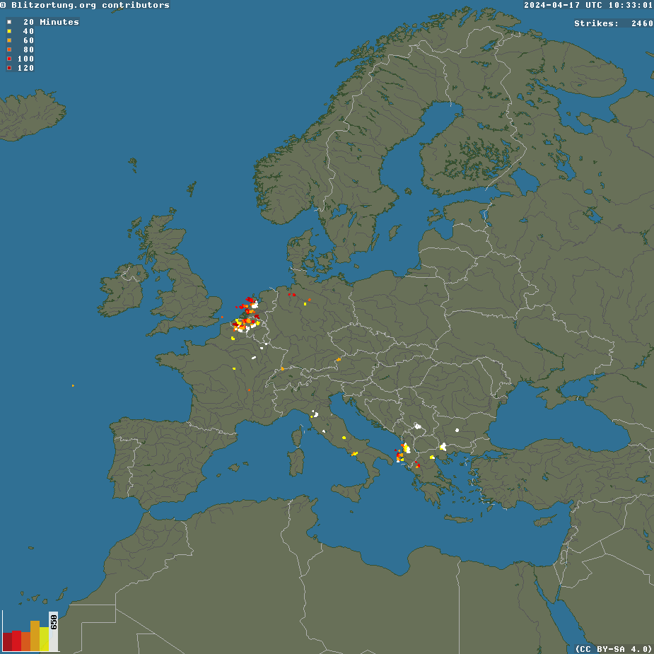 |
| Lightning map of Europe http://www.blitzortung.org/Webpages/index.php?lang=en |
Well, http://www.blitzortung.org/Webpages/index.php?lang=en gives a map showing this data.
Homebrew RF Circuit Design Ideas website
 |
| HA5KHC's useful website |
Unfortunately there is nowhere on the page with a contact address for the website owner, although I expect HA5KHC's details will be on QRZ.com.
UPDATE: Adrian YO5PBG said:
"I believe it is a mirror of the original site... of Iiulian - YO3DAC/VA3IUL - http://www.qsl.net/va3iul/Homebrew_RF_Circuit_Design_Ideas/Homebrew_RF_Circuit_Design_Ideas.htm"
New frequency for LF QRSS3 beacon : 137.766kHz
Using the strong German commercial station DCF39 on 138.830kHz (it is S9+ with me) as an accurate frequency reference, I have
checked the frequency of my QRSS3 QRP beacon and it is running higher up
the band than I thought due to the way the crystal is loaded.
Frequency to look is 137.766kHz +/- . It should be within 1Hz of this frequency.
Reports and screenshots (looking now in the right place) would be very much appreciated. I shall leave the beacon running all today at QRSS3 speed.
Frequency to look is 137.766kHz +/- . It should be within 1Hz of this frequency.
Reports and screenshots (looking now in the right place) would be very much appreciated. I shall leave the beacon running all today at QRSS3 speed.
22 Jan 2013
137kHz E-field probe mag-mount
 |
Tiny E-field probe on the car roof on mag-mount |
QRSS3 tests with QRP on 137.685kHz.
This afternoon I started my tests on the 137kHz band again. With my 8W (RF out from the unit - ERP will be uW level) crystal controlled beacon sending QRSS3 feeding the 20m spaced earth electrodes, currently under 8cm of snow, I ventured forth in the car complete with an E-field probe built into the bottom of a mag-mount antenna on the car roof. The E-field probe whip is about 12-15cm long only. It looks like a small UHF quarter wave, rather than an antenna for 2200m! The TX frequency is currently around 137.685kHz and this QRSS3 beacon will remain on overnight. I am hoping that stations out to around 100km will take a look for it.
Well, results have been spectacular with some excellent signals around 8.2km away in the line of the earth-electrodes. Orthogonally, the signal was not copyable at all at a similar range. This is classic loop directionality again.
The receiver consists of the 10-15cm long E-field probe feeding the FT817 with IPO button pressed (improves sensitivity when ON at 137kHz) feeding the PC running Spectran at 0.34Hz resolution.
I do find it unbelievable that such a TX "antenna" buried under the snow with NOTHING in the air at all and with earth rods just 20m apart can put out such a decent signal on the 2200m band.
 |
| QRP earth-electrode antenna signal at 8.2km on 137kHz band |
 |
| /M RX signal at 6km orthogonal to TX antenna. |
I do find it unbelievable that such a TX "antenna" buried under the snow with NOTHING in the air at all and with earth rods just 20m apart can put out such a decent signal on the 2200m band.
21 Jan 2013
New ERP calculations on 472kHz with earth-electrode antenna in 8cm snow
With several repeatable ground wave reports on 472kHz WSPR using the earth-electrode antenna, it is time for a recalculation of my ERP based on a formula (for 500kHz) supplied some years ago by M0BMU. The assumption (from M0BMU, that I am not at all sure is right) is that the noise floor is around 3uV/m in a 2500Hz (WSPR) bandwidth. So, based on the WSPR S/N ratio the field strength when using the earth-electrodes can be calculated.
Conclusions
I am totally puzzled: measuring antenna current on the Marconi I get ERPs that are an order of magnitude higher yet measured results with the earth-electrode antenna average just 8dB down on the Marconi. This suggests ERPs for the earth-electrode antenna in the low mW region, which I find much more believable.
Any thoughts please?
- G3ZJO at 79km gets me at around -19dB giving my field strength around 355nV/m.
- G3XDV at 61km he gets me around -12dB S/N giving my field strength around 810nV/m.
- M0BMU at 69km he gets me around -30dB S/N giving a field strength around 100nV/m
- ERP using G3ZJO's results = (E*d)^2 / 49; with E = 355nV, d = 79km ERP = 16uW
- ERP using G3XDV's results = (E*d)^2 / 49; with E = 810nV, d = 61km ERP = 49uW
- ERP using M0BMU's results = (E*d)^2 / 49; with E =100nV, d = 69km ERP = 1uW
Conclusions
I am totally puzzled: measuring antenna current on the Marconi I get ERPs that are an order of magnitude higher yet measured results with the earth-electrode antenna average just 8dB down on the Marconi. This suggests ERPs for the earth-electrode antenna in the low mW region, which I find much more believable.
Any thoughts please?
Is this Chinese HF radio a wind up one?
As the person who started the FT818 hare running a year or so back (my thoughts and ideas for an FT817 replacement - thanks to a little Photoshop editing!) , I'm wondering if the attached is real or also a spoof?
It purports to be a new Chinese HF radio retailing for £299. It looks very much like an IC718 with some stickers on. It was brought to my attention by Steve G1KQH who found it at
http://s3.zetaboards.com/copyt
 A real Chinese HF radio at this sort of price is not totally out of the question: labour costs are low and there are already some very nice Chinese VHF/UHF handhelds on the market that under-cut Yaesu and Icom by around 100%. It is surely just a matter of time before an FT817 or an IC718 look-alike radio is available from one of the Chinese makers.
UPDATE 1755z: maybe this IS real. See http://www.tradekey.com/product-view/1538868-518398/Hf-Transceiver-ft-808-.html
It purports to be a new Chinese HF radio retailing for £299. It looks very much like an IC718 with some stickers on. It was brought to my attention by Steve G1KQH who found it at
http://s3.zetaboards.com/copyt
UPDATE 1755z: maybe this IS real. See http://www.tradekey.com/product-view/1538868-518398/Hf-Transceiver-ft-808-.html
Back on the earth-electrode antenna on 472kHz
 |
| The red dots show where the wire to my far earth rod goes - under the snow! |
I am signing G3XBM/1 on the WSPR database to distinguish my signal from that transmitted using a Marconi where I use G3XBM. I hope no-one minds me using this suffix for a short period, but it is very much in the interests of good research. The signal level with G3XDV at 61km is about 8dB weaker on the earth-electrode antenna than on the vertical Marconi.
20 Jan 2013
ILER-40 and ILER-20 QRP SSB transceiver kits
The ILER-40 and ILER-20 are low cost, simple 4-5W QRP SSB transceivers for 40m and 20m from Spain, designed by Javier EA3GCY. They are designed around NE602 ICs working bi-directionally to save parts.
Built on a 12 x 10cm PCB, they look easy to build. Details are available at http://www.qsl.net/ea3gcy/ . The price is a snip at just 67.50 euros plus 10 euros shipping. It looks a very well engineered kit.
See http://www.eham.net/reviews/detail/10700 for a number of (very good) reviews of this kit which looks like a neat introduction to QRP SSB operation. Kits now being supplied include a small AGC sub-board. The kit does not include a microphone or case.
Built on a 12 x 10cm PCB, they look easy to build. Details are available at http://www.qsl.net/ea3gcy/ . The price is a snip at just 67.50 euros plus 10 euros shipping. It looks a very well engineered kit.
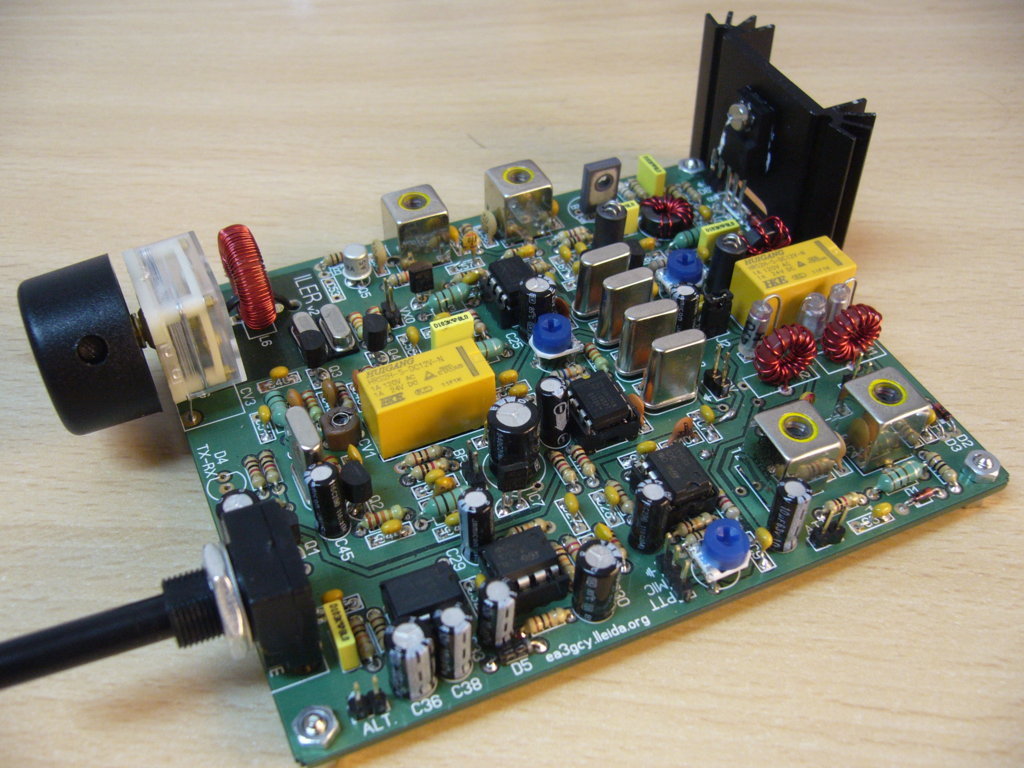 |
| ILER-40 (and ILER-20) QRP SSB kit from EA3GCY |
IC7100 price

An IC7100 at that price is rather more than I would want to pay, but if it was to last 12 years like my current FT817 already has, it might be worth it, especially with 4m, 2m and 70cm coverage. On the other hand, a second (additional) FT817 would do all I really need at under a third of the price!
E-field probe mag-mount now built

The present design is a poor man's PA0RDT probe but using an MPF102 and a 2N3904 rather than the better devices used in Rodolph's high IP2/3 design. I may put a tuned circuit in the FET drain to increase the gain at 137kHz and reduce the gain outside the band. I will experiment with this before going out in the car.
Currently it is snowing continuously here, so road testing the EFP and checking coverage of my QRP 137kHz CW and QRSS3/30 beacon will now have to wait until later in the week.
UPDATE: I have modified the EFP so that the FET output comes from the drain with a drain tuned circuit tuned to 137kHz. I have the source resistor not decoupled initially but will consider adding this if I need a little more overall gain as the barefoot FT817 is very deaf on 137kHz.
19 Jan 2013
A mag-mount as an E-field probe for 137kHz
Next week, assuming the snow has gone, I want to drive around the local area to plot the polar pattern of my earth-electrode antenna working on 137kHz. My 7-8W beacon transmitter can send a range of QRSS and CW messages, so I want a way of driving to different places using my FT817 fed via a preamp and measuring the S/N using Spectran whilst remaining inside the car.
Portable RX loops are fine, but these are directional and need to be set up each time a measurement is taken outside of the car. Ideally I need an omni-directional RX antenna like an E-field probe. So, I'm looking for a way to drive to a spot, take a quick measurement from inside the car, then move on; a loop works, but when it is -2 deg C outside and the ground is icy, it is not ideal.
Either I put the electronics for an E-field probe right at the base of the mag-mount (mechanically not ideal) or I have the electronics in the car and somehow tune out the coax cable capacitance. At the moment I am still experimenting to find an arrangement that works with good sensitivity by checking the strong Greek commercial signal just outside the 137kHz band.
Based on 472kHz results, the earth-electrode antenna behaves like a loop with loop-like directionality. I 'd expect to see the same pattern on 137kHz.
K7AGE video of his KX3 build
Randy K7AGE has done a wonderfully amusing video of him building his Elecraft KX3. I won't spoil the fun, but recommend you watch it and see how it is done.
18 Jan 2013
Square trade eBay Warranties - any good?
Just looked on eBay for various amateur radio items and noticed the Albrecht AE2990 10,11,12m handheld on sale from various UK suppliers from around £150. Now also shown was an optional 3 year warranty - see http://pages.ebay.co.uk/safetycentre/buyingwithconfidence/warranties/index.html which cover failures to the device outside the manufacturer's warranty period. So, for less than £200 you can have a multimode HF handheld complete with 3 yr warranty.
My question is this. Has anyone here bought an eBay item with one of these warranties - they seem to be widely offered - and had to make a claim? It sounds almost too good to be true. These warranties are also available on low cost VHF/UHF handhelds as well where the warranty cost is only around £8-9, which looks remarkable value if the product fails. This is as long as the warranty is a decent one that is honoured and the small print doesn't render it worthless. They also offer a 5 day repair or replacement service.
 |
| Peace of mind 3yr warranty for £27 - too good to be true? |
Mixed results with WSPR-X and WSPR-15
The new version of WSPR works well with plenty of reports given and received on 472kHz with it over the last 12 hours using the 2 minute version (as before but now with a waterfall and better interface), but mixed results on the slower 15 minute slot WSPR-15 which can detect much weaker signals.
My problem is TX drift over a long 15 minute transmission. My small 10W transverter is in a tiny plastic box. When using a 2 minute transmission the PA barely gets warm so there is little heat transferred to the crystal oscillator. With the much longer TX burst the PA warms more and the crystal warms up several degrees, moving the oscillator frequency by some 10s of Hz. So, although I was able to copy signals in WSPR-15, I was not able to be detected by others overnight. There are also far fewer stations monitoring yet on WSPR-15.
The solution is to rebuild the transverter into a bigger (metal) box with (a) better heatsinking so the heat rise with a mismatch is lower, (b) a slightly more efficient PA - problem here is with weather changes the antenna match goes off optimum sometimes and the heat rises as it the PA becomes less class E, and (c) put the conversion frequency oscillator physically further away from the PA, currently it is less than 10cm.
If I fix these issues and am sure that I transmit a more stable signal in the narrower (25Hz wide) WSPR-15 slot then I have a better chance of succeeding with the more sensitive version. With another 7-9dB S/N detection improvement, my signal could reach some of the more distant stations like TF3HZ.
17 Jan 2013
Iceland get the new MF band
Icelandic radio amateurs have been granted access to 472-479 kHz and temporary permits for 1850-1900kHz, 5.260-5.410 MHz 70.000-70.200 MHz have been extended.
WSPR-X and WSPR-15
A note from Joe Taylor K1JT informing us about a new version of WSPR.
WSPR-X and WSPR-15
Wed Jan 16, 2013 8:23 pm
Some of you may be interested in trying WSPR-X, a new version of WSPR that includes the slow mode WSPR-15. WSPR-15 uses 15-minute T/R sequences, rather than the standard 2-minute sequences; at MF and LF it is 9 dB more sensitive than WSPR-2, decoding signals as weak as -37 dB in the standard 2500 Hz reference bandwidth. WSPR-15 is not recommended for use at HF: the tone spacing is only 0.183 Hz, less than the Doppler spreading typical of many HF paths. The main intended application for WSPR-15 is for very difficult paths at 137 kHz and the new 472 kHz band. It may be interesting to try on 160 meters, as well. Note that the recommended WSPR-15 sub-band is a 25 Hz slice just above the 200-Hz WSPR-2 sub-band, i.e., 1600-1625 Hz above the standard "dial Frequency". This will be handled automatically if you set up WSPR-X in the normal way.
A brief online User's Guide for WSPR-X is posted at
http://www.physics.princeton.edu/pulsar/K1JT/WSPR-X_Users_ Guide.pdf ,
and the Windows installation file is posted at
http://physics.princeton.edu/pulsar/K1JT/WSPRX_07r2948.exe .
At present, WSPR-X does not support I/Q audio (for use with direct conversion receivers and transceivers) and does not do “band hopping”. Otherwise most familiar WSPR features are present and working well.
For software enthusiasts: Unlike older versions of WSPR, the user interface of WSPR-X is written in C++ and the Qt programming framework. My expectation is that this shift will make for easier development and program maintenance in the future. At present a click-to-install package is available only for Windows. Source code for WSPR-X is available from the open-source SVN repository at berlios.de. Anonymous checkout of the full WSPR-X source code can be accomplished with the command svn co svn://svn.berlios.de/wsjt/branches/wsprx
User comments, suggestions, and bug reports will be very welcome!
-- 73, Joe, K1JT
16 Jan 2013
Band Plans and AM - Feb 2013 RadCom
In the new February RadCom that just dropped on my mat at lunchtime there is a copy of the band plans for all bands from 136kHz to 134GHz. What I fail to understand is why does the RSGB appear so anti-AM?
For many years now there has been a clear choice for an AM centre of activity on 144.55MHz. The RSGB has been made aware of this on many occasions and yet still we have a (begrudging) footnote, just about visible if you look hard, saying this is where to look. Even this comment ends with, "although this frequency is not officially recognised within the 2m band plan". Why not? We have a FAX calling frequency listed and goodness knows how many DV Internet Voice Gateway frequencies listed, yet we cannot be allowed an official AM centre of activity properly listed! AM is not a common mode these days, but those who enjoy the mode need to know where to meet on the band. The RSGB is giving no help at all here.
I also get frustrated with the 10m band plan where AM is again almost treated as a disease. Most AM activity has been in the 29.0-29.1MHz segment for years now: this is THE part of the band where AM users congregate, yet the all-mode section with up to 6kHz bandwidth does not start until 29.1MHz upwards! Does no-one who creates these band plans actually listen to see what actually goes on? In the last 30 years I have had many AM contacts on 10m and not one outside 29.0 - 29.1MHz.
So, next time you consider the band plans, please:
(a) Add an AM "centre of activity" frequency into the 2m band plan - it is 144.550MHz in case you don't know.
(b) Show 29-29.1MHz as the AM sub-band in the 10m band plan.
Back on 137kHz TX
 |
| QRSS and CW beacon TX for 137.685 kHz |
Instead, I ended up building a new CW, QRSS3 and QRSS30 8W beacon transmitter using an IRF640 PA device. This evening and overnight the beacon will run QRSS3 on approximately 137.685kHz and I have requested reports and screenshots.
The antenna being used is my 20m spaced earth-electrode pair set-up used very successfully on 472kHz last weekend. On 137kHz signals are much weaker than on 472kHz, so I await reports with interest.
The whole unit runs quite cool when housed in a plastic box. Switches on the front of the boxed unit allow up to 7 pre-programmed messages to be beaconed at varying speeds. As normal, I use the K1EL beacon chip for the beacon message generation. The signal source is a 3.579MHz crystal in a divide by 26 circuit implemented in a PIC like device and kindly supplied to me by a French amateur Francis F6HSI a few years ago.
15 Jan 2013
eQSL cards
 |
| Brazilian QSL card received via www.eqsl.net |
Checking my totals I see that I have 55 countries confirmed by eQSL cards. All these will be with 2.5W or less on all modes, mostly SSB on 10m and 6m. Many of my DXCC countries pre-date the eQSL era and I have not been that active in DXing as such in recent years, apart from the occasional contest like CQWW SSB, which I enjoy with QRP. As you know, I prefer to carry out crazy experiments somewhat on the edge of sanity on strange bands with odd antennas instead!
More IC7100 photos
 |
| http://www.universal-radio.com/catalog/hamhf/3071.jpg |
14 Jan 2013
Another earth-electrode station on 472kHz
If you spot G4HJW/1 on the WSPR database on 472kHz this is Bernie who is about 9km from me on his 30m baseline earth-electrode antenna. G4HJW is him on his Marconi by the way. Looking at his unique spots, he is getting reports from all over the place: not as good as his Marconi but reports out to over 900km isn't bad (GM, F, PA, G etc).
Next week, after the snow has gone, we hope to have a 2-way CW QSO on 472kHz using earth-electrode antennas at each end. That should be fun!
Next week, after the snow has gone, we hope to have a 2-way CW QSO on 472kHz using earth-electrode antennas at each end. That should be fun!
An INDOOR loop on 472kHz TX?
Over the last few days I have been receiving quite strong WSPR signals on 472kHz from Richard G4KPX who is in Ely, some 14km north east of me. Looking on the WSPR database I see he has been copied up to 573km on the band using WSPR. Now, in a email from Richard today he revealed his secret: he is using just 1W RF into an indoor 3m x 2m single turn loop made of 10mm pipe leaning against the wall of his spare bedroom! The EIRP is at most 100uW and probably a lot less because of the losses with mounting it where he does and the capacitors used to resonate it. This is a pretty amazing set of results.
Richard has been spotted across the Atlantic on 160m using the same indoor antenna and has similar magnetic loop antennas for all HF bands I believe.
So, if you believe you have no space for an MF band TX antenna, and you don't even have a garden to put a couple of earth-electrodes in the ground, you could always follow Richard's example.
Some months ago I believe one of the German 136kHz stations (DF6NM?) tried something similar using a large coax as a big indoor loop on 136kHz and also got some quite decent results. Never say you cannot erect an antenna! What you need is a bit of ingenuity.
.....and NOT a TS-990 - something better!
Just to put some perspective on things, this is a small CW transmitter that just about anyone could build for a few pounds only and use it to work stations all over the world with a modest dipole antenna or similar. The OXO transmitter was designed by GM3OXX and is a classic design.
Power from the OXO is around 800mW - 1.5W depending on the band and on the final transistor and its emitter resistor. I have used this design on HF and had hours of fun with it. Long after a rig like the TS-990 would be gathering dust, this little beauty will carry on giving pleasure with each and every contact.
 |
| http://www.qsl.net/g3pto/OXO.gif |
Kenwood TS-990 - UK price
Well my fellow blog readers, I have some good news for you!
The new Kenwood TS-990 is now available to order for Martin Lynch, and I expect many others, for only £6600 with deliveries expected February. I am sure many will buy this fine radio, but as this is about ten times my budget (once every 10 years or so) for a new HF transceiver, I will not be one of them.
The new Kenwood TS-990 is now available to order for Martin Lynch, and I expect many others, for only £6600 with deliveries expected February. I am sure many will buy this fine radio, but as this is about ten times my budget (once every 10 years or so) for a new HF transceiver, I will not be one of them.
 |
| http://www.jayceecoms.com/images/Kenwood-ts990s-1.jpg |
13 Jan 2013
472kHz update
With nearly 2 weeks of operation on the new band with very low EIRP levels (varying from typically 5-10mW with 100mW on just one occasion) perhaps it is time to summarise how things have been going. A check of the WSPR database shows almost 70 unique reports across Europe of my signals from just a few km away to 1736km. I have still not managed to be copied by TF3HZ in Iceland at just over 2000km and this is my next target. To achieve this will need me to re-erect and better optimise my Marconi vertical. With some optimisation it should just about be possible achieve 200mW EIRP.
On CW I have received a report from over 160km away when I was calling CQ. A JT9-1 QSO with G3ZJO at 79km is still my best 2-way QSO, although I believe it should be possible to work much further with this mode (I worked OR7T in Belgium with it on 500kHz).
So, pretty satisfying results so far. This has been helped by the huge number of stations currently monitoring WSPR on the new band - frequently over 40 people at any one time. Right now there are 59 stations monitoring!
On 136kHz the challenge with small antennas and low power is considerably harder on WSPR as there are too few stations monitoring: even if the signal was getting several hundred km, one can only tell if someone is at the far end and reporting it.
 |
| Unique WSPR spots in the last 2 weeks on 472kHz |
So, pretty satisfying results so far. This has been helped by the huge number of stations currently monitoring WSPR on the new band - frequently over 40 people at any one time. Right now there are 59 stations monitoring!
On 136kHz the challenge with small antennas and low power is considerably harder on WSPR as there are too few stations monitoring: even if the signal was getting several hundred km, one can only tell if someone is at the far end and reporting it.
Solar activity this month
A quick glance at the solar data over the last week or two will convince anyone that things are looking up. Many believe that a second peak, not that uncommon, is likely soon and that this peak will actually turn out to be the real peak of cycle 24. It is some time since we have seen sunspot numbers as high as this for so many days in a row. In the end, the peak is usually based on smoothed sunspot numbers so it will be very many months into the future before we will know if the recent upsurge has helped to make a new smoothed peak.
I see there is a possibility of M or X class flares in the next two days which could affect propagation, although I think it improbable these will be on a scale likely to knock out power stations and satellites. At some future point, most likely long after all of us are long dead and at a time when the cycles return to huge numbers of sunspots, it will happen though. Of course large solar flares can happen at any time, so you never know.
For more data on the recent solar activity see http://www.solen.info/solar/ .
12 Jan 2013
Albrect AE2990 Albrect12/11/10m Multimode handheld
 |
| Albrect AE2990 multimode |
Although I have used the FT817 handheld lots of times on 15 and 10m and had some excellent contacts with it using a small base loaded whip (a counterpoise definitely helps), I have no experience of the Albrecht unit, which looks like an oversized VHF handie.
Has anyone here used one seriously for handheld DXing? If so, how did it perform? The interesting thing is this unit can be programmed for 12m, CB or 10m use by changing some solder pad links under the PTT rubber.
I can imagine that this handheld could provide hours of fun during a summer sporadic-E opening, although I would expect results to be disappointing without a counterpoise if using it handheld with ether the supplied whip or a longer whip.
True handheld DXing can be quite a challenge, but great fun. Actually being able to move the handheld around to get the best angle can sometimes really help, especially on signals coming in at odd angles. Some time ago I was going to see how many countries I could work on handheld SSB, although I've not seriously tried this lately. I much enjoy handheld DXing when on holiday in Devon from clifftop sites overlooking the sea as in these locations many dB can be gained by chosing a nice location with a slope towards the sea. One of my best contacts was a YV station on SSB (8000km) from my late mother's back garden.
Thoughts turning to 136kHz again
After a few weeks on the new 472-479kHz band, my thoughts are again turning to 136kHz, a band that I experimented with a year or more ago now. This band is MUCH harder work than 472 or 500kHz with around 20-30dB more of everything (!) needed. By this I mean that for the same power, the "effort" to get a contact or report seems to be about 20-30dB more. This is partly because the short antennas I use have a very low radiation resistance at 136kHz so losses become more significant. Also, noise can be even more of an issue. Despite all of this, I plan to make a 136kHz version of the transverter I did for 472kHz, but maybe with a bit more RF output (in the 20-30W region). Most of the design is ready done (in my head) so it should only take a few days to do. The plan is to TX using my earth-electrode antenna.
On 136/137kHz there are fewer stations using WSPR, so I will probably use QRSS more. In the past I have made QRSS crystal controlled beacons for this band, but with a transverter and my FT817 I will be able to generate a QRSS signal wherever I want in the band and also be able to have QRSS QSOs.
Does anyone have recommendations for SIMPLE PC program that will allow me to generate QRSS (various speeds) as an audio tone?
This way I can use my SignaLink USB interface and VOX to send QRSS (or DFCW) using audio tones. Please don't suggest Spectrum Lab unless you can give me a "Noddy guide" on how to use it for QRSS! This is a very good program, but to a simple soul like me it seems like you need a PhD to drive it. In the past I've used it for VLF reception, but it took me weeks to work out how to drive it and every time I go back to it I need to learn it all again. I just want a simple QRSS tone generator.
9 Jan 2013
Earth electrode antenna conclusions (472kHz)
With some further tests today I am now able to arrive at some conclusions from my experiments with an earth electrode antenna at 472kHz. Many people including Jim M0BMU and Rik OR7T have been particularly helpful in analysing the data.
These are my conclusions:
 |
| My current 472kHz earth electrode "antenna" - can you see it in the grass? |
- The earth-electrode antenna at 472kHz (2 earth rods in the soil 15-20m apart fed from the TX output) behaves like an H-field loop transmitting antenna.
- It has directivity, with strongest signals in the line of the loop and weakest signals at right angles to it.
- It works as an effective RX antenna too.
- In my environment the loop looks like about 50-60 ohms resistive, so a good match to my transverter directly without matching.
- The structure works because much of the return current flows deep within the soil and rock beneath the earth-electrode antenna. In my case Rik OR7T calculated that the loop area in the ground is effectively 290m sq with a radiation resistance of 0.017 ohm and a loss resistance of 66 ohms.This is a BIG loop!
- Performance compared with my 9m high top loaded Marconi antenna averages only around 8dB down, not a bad figure at all, even with the connecting wire on the ground and not elevated at all.
- Where no other antenna option is available, the earth-electrode antenna is well worth trying both on 472kHz and on 136kHz both for RX and TX. Although it works well here, your geology may be different and results not the same.
472kHz RX and TX with Marconi antenna last night
Overnight I was using a 9m high top loaded Marconi antenna on TX and RX WSPR on 472kHz. I have since taken this down so it doesn't interfere withe the latest earth electrode antenna tests.
The performance of this larger,"in the air" antenna was certainly better than the earth electrode antenna, although not by a huge amount (2-14dB). As you can see, I managed my first transatlantic amateur reception on the new band WE6XGR at 5640km amongst the 27 unique RX spots.
On TX with the same antenna, results were equally satisfying with 34 unique station reports.
The performance of this larger,"in the air" antenna was certainly better than the earth electrode antenna, although not by a huge amount (2-14dB). As you can see, I managed my first transatlantic amateur reception on the new band WE6XGR at 5640km amongst the 27 unique RX spots.
 |
| 472kHz RX spots on Marconi antenna |
 |
| 472kHz TX spots on Marconi antenna |
472kHz earth electrode antenna: nothing in the air
Today, I took my experiments with an earth electrode TX antenna for 472kHz to new levels by placing the connecting wires on the grass i.e. not elevated at all. The theory developing is that the earth electrode antenna works by forming a buried loop in the ground with the earth return path being in the soil and rock beneath the structure. If this is so, then even with the wire sitting on the grass there should still be a loop within the ground, so some radiation from it. Results this afternoon prove this is indeed the case. The following are the results with a 20m baseline between the far earth rod and the copper pipe ground at the home end and with the connecting wire just laying on the grass lawn.
 |
| 472kHz WSPR reports with earth electrode antenna with wire on the lawn |
TS990 Press Release
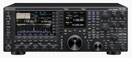 |
| The new TS990 from Kenwood |
I see today that the modern cashbook amateur has a new toy to covet: the TS990 from Kenwood. With a price tag likely to be around £9000 it has to be SOME radio. Looking at the spec it does look very impressive. See http://www2.jvckenwood.com/en/news/2013/20130108.html .
8 Jan 2013
Just one slot of WSPR - 15 reports on 472kHz!
 |
| Reports in just one 2 minute WSPR time slot with 100mW ERP on 472kHz |
How far down is my 472kHz earth electrode antenna on a Marconi?
 This evening I have been noting my WSPR S/N reports from stations across the country and nearer Europe using my 9m long Marconi antenna and comparing these with the reports last night when I was using just the 15m baseline earth-electrode "antenna". I crudely plotted the "improvement factor" in dB on a polar plot. Each dot represents a station reporting my signal with the dB improvement over the earth-electrode antenna plotted on a 0-20dB scale out from the centre.
Although in some directions the difference is very little, in other directions the reports are up to 14dB better on the (omni-directional) Marconi.
Stations with dB improvement using the Marconi antenna
M0BMU 10dB
G0KTN 6dB
G3ZJO 5dB
G3WCB 10dB
DL-SWL 2dB
G4HJW 6dB
M1GEO 14dB
G7NKS 6dB
M0LMH 11dB
G0MQW 10dB
G0MQW 10dB
My conclusion is that the earth electrode antenna is behaving somewhat like a loop with directionality along the line of the earth-electrode baseline and a null off the sides. With stations receiving me off the sides there is most improvement with the Marconi, and less difference with stations end-on who were getting a reasonable signal with the earth-electrode antenna.
CONCLUSION: the simple, stealth, earth-electrode antenna is a VERY useful antenna on 472kHz as long as one is prepared to accept a 2-14dB loss compared with a reasonable Marconi.
RFID chips and credit/debit cards
Many credit and debit cards now have embedded RFID chips to allow contactless transactions in cafes. bars etc. Did you realise that your card's RFID chip could be a way of cloning your card's number and expiry date? Neither did I.
Watch this video to see a demonstration of just how easy it can be to someone with the right technology at his disposal.Sounds like a security loop hole that needs fixing fast.
Watch this video to see a demonstration of just how easy it can be to someone with the right technology at his disposal.Sounds like a security loop hole that needs fixing fast.
A Marconi antenna on 472kHz
So that I can better quantify the performance of my various earth electrode "antennas" I have today erected a 9m long top loaded Marconi vertical for 472kHz. Initial antenna current measurements suggest the ERP is up around 10dB to around 100mW. My plan is to run this overnight again and then tomorrow compare the signal reports against those with my smaller compromise Marconi and my two earth electrode antenna configurations.
7 Jan 2013
Even more fascinating 472kHz experiment
Following on from yesterday's tests, today I started a further test using an earth electrode "antenna" on 472kHz WSPR.
This time I used 2 ground rods in the soil separated by 15m of wire (fed directly from the transverter output at 50 ohms) and powered entirely from a battery supply - PC, FT817, transverter, SignaLink interface - so that there was no connection whatsoever to the house mains earth or copper pipes in the house. The power out would have been slightly lower (lower supply voltage) and the baseline 25% shorter.
So far, results are almost identical to those obtained yesterday when one side of the earth electrode system was connected to the copper pipes in the home on one end.
My best DX WSPR report this evening with 10W RF out from the transverter into the 15m separated electrodes is G0KTN at 210km. ERP is in the low mW region at best. On RX DJ8WX has been copied at 643km.
Although a large Marconi antenna will be far better, this set-up certainly works and gives highly credible results. Considering just how simple this is I hope others experiment with the earth electrode "non antenna" and see how they get on.
UPDATE: Best DX report of my few mW ERP signal with 15m spaced earth electrodes was from DL-SWL at 701km. I am copying lots of signals including SM6DHZ and DK7FC even after breakfast time. Amazing.
This time I used 2 ground rods in the soil separated by 15m of wire (fed directly from the transverter output at 50 ohms) and powered entirely from a battery supply - PC, FT817, transverter, SignaLink interface - so that there was no connection whatsoever to the house mains earth or copper pipes in the house. The power out would have been slightly lower (lower supply voltage) and the baseline 25% shorter.
 |
| 472kHz earth electrode "antenna" system in garden |
My best DX WSPR report this evening with 10W RF out from the transverter into the 15m separated electrodes is G0KTN at 210km. ERP is in the low mW region at best. On RX DJ8WX has been copied at 643km.
Although a large Marconi antenna will be far better, this set-up certainly works and gives highly credible results. Considering just how simple this is I hope others experiment with the earth electrode "non antenna" and see how they get on.
UPDATE: Best DX report of my few mW ERP signal with 15m spaced earth electrodes was from DL-SWL at 701km. I am copying lots of signals including SM6DHZ and DK7FC even after breakfast time. Amazing.
6 Jan 2013
Analysis of 472kHz antenna tests today
With several hundred WSPR spots of my QRP signal received today on 472kHz, I have tried to do a crude analysis of the difference in performance between my short (1/100 wavelength long) Marconi and my earth electrode (ground) antenna. I did this using MS Excel. Now I have forgotten most of the things I knew about Excel, so this is basic stuff here!
I plotted the maximum and minimum signal reports for each type of antenna for a number of different reporting stations and plotted a graph showing the difference and the angle the station is from me to see if there was a clear directionality in the earth electrode system.
Conclusion? I'm not sure, although the difference between the 2 antennas varies from as little as 0.5dB (PA3ABK) up to 16dB (M1GEO) with an average additional loss of around 7dB. Can you see any indication of directivity in the earth electrode antenna? I am assuming the Marconi is omni-directional, which of course may not be the case.
Not bad for an antenna that is invisible to the neighbours and still is capable of getting reports (so far) to 701km away with a few milliwatts ERP.
I plotted the maximum and minimum signal reports for each type of antenna for a number of different reporting stations and plotted a graph showing the difference and the angle the station is from me to see if there was a clear directionality in the earth electrode system.
 |
| Analysis of signal levels with short Marconi and Earth Electrode antenna at 472kHz |
Conclusion? I'm not sure, although the difference between the 2 antennas varies from as little as 0.5dB (PA3ABK) up to 16dB (M1GEO) with an average additional loss of around 7dB. Can you see any indication of directivity in the earth electrode antenna? I am assuming the Marconi is omni-directional, which of course may not be the case.
Not bad for an antenna that is invisible to the neighbours and still is capable of getting reports (so far) to 701km away with a few milliwatts ERP.
Codar AT5 transmitter
 |
| Image on G3XTZ's Radio Museum website |
The AT5 was a small valve TX producing around 10W on 160m and 80m. Using the AT5 we could work right up the English Channel in daylight on AM and CW over a mostly sea path. I noticed a page about the AT5 on the W3EEE website and it took me back 45 years.
 |
| Image on G3XTZ's Radio Museum website |
Nowadays in a volume less than half that of these rigs one can have a complete multi-mode HF-VHF-UHF transceiver with performance far exceeding the AT5 and T28. We forget how much our hobby has changed.
Subscribe to:
Posts (Atom)


