When I had my kitchen refitted recently, the workmen had one of these radios on the go all the time. I guess they are designed to be rugged and stand a lot of abuse. Theirs was covered in plaster and dried on dust but it still managed to work! They are not cheap and not that small, but I guess it is "horses for courses" as they say. Any readers used one of these?
Makita BMR-101 Job Site Radio with DAB + AC Power Adaptor (Blue) (Google Affiliate Ad)
15 Oct 2012
32km test on 8.9775kHz VLF
Tomorrow evening, Oct 16th, at 1700z I'm starting a 24 hour continuous
carrier transmission on 8.9775kHz using my earth-mode system and 5W
beacon TX. The carrier will be dropped for a few hours at some time (not
previously disclosed) during the transmission to help later ID.
Chris G3WCD, who is 32km west of me, is trying to see if anything at all is detectable from my earth-mode set-up at that distance. We both do not realistically expect success, but with the ability to look in uHz bandwidths using Spectrum Lab it is worth a go.
If there is anyone else closer to Burwell, Cambs JO02DG85VD who wants to try looking as well, please let me know ASAP. Ideally stations in the 10-20km range.
14 Oct 2012
MF WSPR activity at an all-time high
 |
| MF WSPR activity this evening |
Best DX yet on 8.97kHz earth-mode: 6km QRSS3
Today I went out to my usual test sites to check the performance of my latest VLF earth-mode system. For the first time, my RX loop and preamp could be optimally tuned in the field. At 1.6km the 8.978kHz QRSS3 beacon signal was rock solid (see first image).
I then moved on to a number of other locations eventually arriving at a spot 6km from the 5W TX where previously I'd only ever managed copy with a constant carrier or QRSS30 (30 second dot CW). This time the signal was about 10dB over noise in 0.67Hz bandwidth on QRSS3, my best ever result at this range (second image).
In the coming week I'll be looking for a new RX test location around 7km or further from the home QTH in the hope of increasing my through-the-ground DX record.
 |
| 5W 8.978kHz QRSS3 earth-mode signal at 1.6km (STRONG) |
 | |
|
In the coming week I'll be looking for a new RX test location around 7km or further from the home QTH in the hope of increasing my through-the-ground DX record.
13 Oct 2012
500kHz WSPR Spots
Conditions on HF appear to be very disturbed (according to the propagation forecasts) yet I'm getting plenty of WSPR spots on 500kHz. It will be much better when we all get access to 472-479kHz as, currently, activity on MF is split between this band and 500kHz.


SAQ (17.2kHz) transmission Oct 24th

IC7100 for 1 penny??
Amused to see the Nevada advert for the Icom IC7100 on their website. At this price I would expect this high end mobile/home station multimode to be sold out!
 |
| Nice price for the IC7100 ! |
Earth-mode VLF RX kit updated
Today I've been updating my VLF receiving kit ahead of doing some further field tests, probably on Monday. I've now changed my RX loop so that the resonance can be adjusted in the field using a capacitance switch box to bring it to resonance. The capacitance to bring it to resonance is around 240nF. The loop was about 1kHz off-tune so that the signal was around 4-6dB weaker than it should have been. Now I can tune the loop for maximum S/N in the field and can adjust the loop to a variety of test frequencies. I've also peaked the 8.97kHz tuned circuit on my earth-electrode receiver input and fixed a faulty connection cable.
Whether these changes will allow me to get any further through the ground remains to be seen.
Whether these changes will allow me to get any further through the ground remains to be seen.
What a 500kHz WSPR signal looks like
G6AVK has his temporary grabber running on 500kHz this evening. See http://www.qsl.net/g6avk/ . It was interesting to see what my WSPR signal looks like on a grabber at around 80km away. My report was -24dB S/N but, as you can see, it is clearly visible FSK keying around 6Hz.


12 Oct 2012
G3ZJO builds the G3XBM MF transverter
Over the last few days Eddie G3ZJO has been building a near carbon copy of my 10W transverter for 472/500kHz. I am pleased to hear that the build went well and Eddie is getting well over 10W RF from the unit.
Eddie found a couple of errors on my schematic (values shown on my photo are wrong on the circuit) and these I must correct. Once these had been sorted - my fault - the transverter worked fine. I see Eddie is getting some good reports on 500kHz WSPR this evening.
If anyone else builds a copy, please let me know and send me a photo.
 |
| G3ZJO's (very neat) version of my 472/500kHz transverter |
If anyone else builds a copy, please let me know and send me a photo.
11 Oct 2012
Earth-mode 8.97kHz VLF tests
Today I did the first tests using my new 5W 8.97kHz beacon looking for signals at my usual "close" test site 1.6km from the home QTH. Good copy on QRSS3 and even solid copy on 10wpm CW. Copy was using my 30t 80cm loop on RX although results were similar using a 5m spaced earth electrode pair. Tests at greater range over the weekend. This is a recording of the 10wpm 8.97kHz CW signal at 1.6km .
As the traces show, there are a lot of strong interfering signals around in this part of the spectrum. With an E-field probe there were lots of telemetry like signals audible which I think are being carried over the national grid overhead cables. These were about 0.5km away from the test site.
 |
| QRSS3 signal at 1.6km using a 30t 80cm loop on RX |
 |
| 10wpm signal at 1.6km using a 30t 80cm loop on RX |
9 Oct 2012
Ten-Tec Argonaut VI
Ten-Tec is working on a new QRP radio that is a little larger than the FT817 but with a more conventional styling than the KX3. At the moment I understand price has not been fixed. 25 pre-production units are being field tested. First shipments are not expected until later this year and there are hints that this may slip.
 I am ambivalent about this new design: with limited HF band coverage and no VHF/UHF coverage and a styling that is "plain Jane" how many people will opt for it compared with (a) a new KX3 or even (b) an FT817 despite it being a 10 year old design? It needs to have some pretty strong unique selling features I think.
Interestingly, the Ten-Tec website makes no mention of this radio as far as I can see. Elecraft were forward selling the KX3 nearly a year before it made it out to first customers. Why is Ten-Tec not already seriously warming up the market? Surely if it is to be worth buying they should be encouraging potential customers not to buy a KX3?
The image above is linked from the www.qrper.com website.
Improved Software VLF Receiver
 |
| SWL Roland's enhanced SM6LKM software VLF receiver |
- 44.1k/48k/88.2k/96k/176.4k/192k sample rate support
- More CW filters, SSB filter and AM filter added
- Spectrum display for audio frequency
- File-I/O for *.wav format (16bit)
- Left/Right channel select
- RMS signal level bar for audio level
- Muting (M) key
- Time+Date display, UTC or local time
To use the receiver all that is needed is a VLF signal feeding into the mic input of the PC. Be sure you know what you are doing: the usual safe thing to do is to put a couple of back-to-back diodes across the DC isolated VLF input to prevent damage to the sound card. With an E-field probe antenna this receiver is capable of receiving many VLF transmitters from around the world. I shall be using it in future to monitor my 8.97kHz earth-mode CW beacon when out in the field testing.
New VLF Beacon TX
Today I completed the build of my new VLF beacon transmitter. The beacon puts out 5W into a 50 ohm load, which is very close to the resistance of my 20m spaced earth electrodes. The beacon operates at either 8.970kHz or 4.485kHz with (a) continuous carrier, (b) 10wpm CW or (c) QRSS3.
The main changes were to separate the keyer and the PA, mount the whole unit in a larger metal box and to use a 3C90 matching transformer with a fixed turns ratio having measured the ground resistance, which does not change greatly. On a continuous carrier soak test the case temperature only rises about 10 deg C, so frequency drift in the oscillator divider frequency source should be only around 0.1Hz at final frequency.
Having got the beacon finished, the next stage is to start work on some improved receiving kit and to see what sort of range can be achieved through the ground. My best DX so far with the original beacon was 6km, but this is certainly not the limit.
| VLF Earth-mode Beacon Transmitter |
Having got the beacon finished, the next stage is to start work on some improved receiving kit and to see what sort of range can be achieved through the ground. My best DX so far with the original beacon was 6km, but this is certainly not the limit.
8 Oct 2012
iPod Touch 4g - resetting

So, I backed up the photos and videos, ensured the apps were safe on the main PC and pressed the "reset". Then I loaded iOS6.0 and all the apps back on the iPod. First impressions are that the battery life has just about doubled and appears to be almost back to what it was 2 years ago. I wasn't expecting this. To be honest, it feels like a brand new machine.
Although I don't buy that many modern gadgets the purchase of the iPod Touch 4g 2 years ago was one of my best ever purchases. It allows me to keep in touch with my emails, BBC, family by Skype and FaceTime video, WSPR spots monitoring, take photos and videos, Facebook, etc wherever there is a WiFi connection. It slips in my pocket and is an almost constant companion.
My whole family are Apple converts!
6 Oct 2012
Latest sunspot news
The latest from NASA:
 The latest prediction graph from http://solarscience.msfc.nasa.gov/images/ssn_predict_l.gif
The current prediction for Sunspot Cycle 24 gives a smoothed sunspot number maximum of about 75 in the Fall of 2013. The smoothed sunspot number (for 2012/02) is already nearly 67 due to the strong peak in late 2011 so the official maximum will be at least this high. We are currently well over three years into Cycle 24. The current predicted and observed size makes this the smallest sunspot cycle since Cycle 14 which had a maximum of 64.2 in February of 1906.

Charity jazz concert, Oxford Sunday Oct 7th

 |
| Tim in one of his many appearances at Ronnie Scott's in London |
Over-the-horizon on 480THz

Together, the QRO optical beacon running from home, focussed with a 100mm lens (gain about 24-30dB), and a portable high sensitivity 100mm lens based detector should allow plenty of scope for innovative NLOS tests on dark winter evenings.
Just realised: 5W out (for example) into a 30dB gain lens "antenna" is equivalent to 5kW of light power in the beam. That is SOME bright light. Clearly great care is needed in siting and aiming such a system to ensure safety.
4 Oct 2012
New soldering iron needed
My old Weller soldering iron station (an old Pye Telecom chuck-out from about 1980) is on its very last legs - it is physically cracked and really does need replacing. You can tell how old it is by the mains wire colours! It was possibly the one I had on my bench when I started work in 1970.
I'm looking at the Maplin soldering iron range for a replacement, which look good value. Most of my work is with discrete parts but increasingly some SMA parts are being used too. Up to now I have been using up my stock of tin-lead solder, but am happy to move to lead free.
So, please may I have your recommendation on what soldering iron to go for?
I don't mind spending a bit more if by doing so I get a more reliable soldering station. Clearly replacement tips must be available inexpensively.
3C90 cores at 8.97kHz
The output of my TDA2003 based VLF earth-mode transmitter is around 5W into 4 ohms. The new semi-permanent earth mode "antenna" just installed measured at around 50-60 ohms resistive at 8.97kHz. I used an AC potential divider technique to check this. Today I wound a small 3C90 based transformer using the advice I got from various people yesterday and it works very well, matching the TDA2003 perfectly to the earth electrode pair. I managed to destroy my K1EL message keyer's 5V regulator (and the keyer IC too!) so a rebuild is required before I go out into the field again to do some RX measurements. All being well these new tests will start in the next few days.
My SFH213 PIN photodiodes arrived today and my 12W Phlatlight LEDs are due next week. I'd better crack on with the new VLF earth-mode tests before these arrive as I will want to try some over-the-horizon 481THz tests with the more powerful optical transmitter and more sensitive detectors.
My SFH213 PIN photodiodes arrived today and my 12W Phlatlight LEDs are due next week. I'd better crack on with the new VLF earth-mode tests before these arrive as I will want to try some over-the-horizon 481THz tests with the more powerful optical transmitter and more sensitive detectors.
More on LF transformers
Following on from the earlier blog entry about using a 3C90 core for a VLF and LF transformer, I got this reply from Jim M0BMU last night on the RSGB LF Yahoo group. I post it here as it contains some useful additional information. See also the mini-Ring Core Calculator from DL5SWB at http://dl5swb.de/ .
"Dear Roger, Andy, LF Group,
>> Four turns minimum for 137kHz 25 Watts. 60 or so for 9kHz
> Yes these values look quite practical ones.
...But now the inductance of the winding and AL value of the core do become important. (BTW, the value of 2000 is the relative permeability of the 3C90 material. The "inductance factor" AL, the "inductance per turn-squared", is a different number which depends on the shape and size of the core as well as the permeability.) AL for this core is given as 2690nH nominally. With a four turn winding, the resulting L is about 43uH, with a reactance of only 37ohms at 137k. In a 50 ohm circuit, this will cetainly mess things up a bit. As a general rule, you would probably like the reactance of the 50ohm winding to be at least 250ohms at the operating frequency. This requires an inductance of more than 290uH, so a winding of 11 turns minimum will be needed for a 50ohm impedance level.
This is a typical result when using a core that is much larger than what is required by power handling considerations - the number of turns needed to keep the flux down to an acceptable level becomes so small that the inductance becomes the deciding factor. It also obviously makes it tricky to match to low impedances, which is often what you are trying to do in a PA or
loop-matching transformer - you may well find that you end up with windings of less than 1 turn! In these cases the inductance or the required turns ratio becomes the determining factors. In the more normal situation where you are trying to design a transformer with an economically-sized core for a given power level, the inductance is usually large enough not to be an issue, as Andy stated.
At 9kHz however, the 60turn winding is quite reasonable from the inductance point of view, giving 9.7mH and about 550ohm reactance. Also, the core losses would be lower at 9kHz, so you could allow a higher flux density and reduce the number of turns (or increase the power level, which might be better!)
Cheers, Jim Moritz
73 de M0BMU"
Azores Islands

3 Oct 2012
On-line LF toroid transformer design tool?
I have some 42mm diameter 3C90 toroids and want to use these in output transformers in 3 applications:
(1) in the output of a 137kHz (up to) 25W transmitter
(2) in the output of an 8.97kHz (up to) 25W transmitter
(3) as an impedance transformer for a TX loop antenna at 8.97, 137 and 500kHz.
I was looking for an on-line calculator to help me work out secondary turns needed, but could not find one. Andy G4JNT helped with this input:
As an aside, I use http://www.66pacific.com/calculators/toroid_calc.aspx very often to work out the turns needed for the common HF toroids such as T37-x and T50-x.
(1) in the output of a 137kHz (up to) 25W transmitter
(2) in the output of an 8.97kHz (up to) 25W transmitter
(3) as an impedance transformer for a TX loop antenna at 8.97, 137 and 500kHz.
I was looking for an on-line calculator to help me work out secondary turns needed, but could not find one. Andy G4JNT helped with this input:
To aid calculations in future I have produced a small spreadsheet to work out the secondary turns from the input data (freq, cross sectional area and RF power out)."The magic equation is Vrms = 4.44.F.N.A.B all in SI units.rearranged Nmin = V / (4.44 . F . A . B)Al is irrelevant for transformers.Use a Bmax of 0.1 Tesla for Ferrites, allowing a decent safety margin.Your A (of 25 mm^2) = 25*10^-6 , F = 137000,25W in 50 ohms is 35V"
As an aside, I use http://www.66pacific.com/calculators/toroid_calc.aspx very often to work out the turns needed for the common HF toroids such as T37-x and T50-x.
2 Oct 2012
A return to earth-mode VLF experiments
This afternoon I installed a more permanent earth-mode ground system to use in forthcoming tests at VLF through to 500kHz. Instead of bringing the 2 earth connections into my upstairs shack, as I had done previously, I have now installed a couple of grounds and wires that come into my "designing" shack downstairs. This means I can now run a lot more tests using the test equipment at my disposal. It also means I do not tie up equipment in my "operating" shack upstairs when doing earth mode beaconing.

The diagram shows the current arrangement of the grounds and wire. At its highest point the wire is 1.5m above ground, running along the back garden fence. It is invisible.
Tomorrow I hope to get the ULF/VLF earth-mode beacon TX on-air initially on 8.97kHz and 1.147kHz in QRSS3 and QRSS30 and carry out my usual reception test at a point 1.6km from home where the signal is usually strong. Subject to satisfactory results with the new TX "antenna" I then intend to do a series of RX tests using new equipment out to around 10km from home.

Tomorrow I hope to get the ULF/VLF earth-mode beacon TX on-air initially on 8.97kHz and 1.147kHz in QRSS3 and QRSS30 and carry out my usual reception test at a point 1.6km from home where the signal is usually strong. Subject to satisfactory results with the new TX "antenna" I then intend to do a series of RX tests using new equipment out to around 10km from home.
The OXO QRP transmitter
 |
| OXO schematic on the G3PTO website |
One of the most simple and popular HF transmitters is the OXO, originally design by GM3OXX. The circuit appeared in the GQRP club's SPRAT magazine about 30 years ago. It is essentially a 2 transistor QRP transmitter (plus another for keying) capable of working as a fundamental crystal controlled or VXO controlled transmitter on an HF band. I used this design as the TX part of my Pipit 800mW transceiver for 15m and later the Tenner transceiver for 10m. On the higher bands there is more chance of a little chirp, but perfectly usable. On the lower HF bands the OXO is capable of over 1W. It is a very easy transmitter to build, is almost guaranteed to work first time, and is great fun to use.
As it is some time since I've built one, I might just knock one up this afternoon and see how I get on, perhaps on 80m or 40m CW.
29 Sept 2012
QRO optical beacon for over-the-horizon tests
 |
| 12W red LEDs for optical beaconing |
My original beacon circuit is shown below and was a good signal over the horizon 3.6km from home when using Spectran to show the received signal, which was not even visible to the naked eye or audible in a headset. I am hoping that a very similar circuit will work for the Phlatlight LED beacon.
Autumn Projects Update
About 6 weeks ago I listed a number of projects that I wanted to do this autumn. Here is a progress report.
- Finish the 472kHz transverter and write this up. DONE
- Simple 28MHz QRP WSPR transceiver to use with a netbook. DONE (but the TX only beacon is boxed)
- Stand alone 137kHz receiver (for use with PC).
- Semi-permanent E-field probe antenna and on-line 137kHz/472kHz grabbers
- More non line-of-sight light beam experiments (get better distances). 12W Phlatlight LEDs and more sensitive SRF213 detectors ordered
- Semi-permanent 481THz QRSS beacon for NLOS light beam tests.
- Alternative HF antennas - maybe re-erect my Par Electronics 40/20/10 end-fed.
- Further earth-mode (ground conduction) experiments - tests at around 30 and 73kHz as well as more tests at VLF aiming to improve best though ground DX (currently 6km with 5W). More permanent earth-mode "antenna" erected.
- Experiment with horizontal loop antenna on TX at VLF (maximising coupling into ground).
- Build some better LF/MF test gear such as resistive SWR bridge, 50W dummy load and a noise bridge.
28 Sept 2012
Operating 10m QRP SSB
Today I took a break from designing and building innovative new stuff to enjoy 10m SSB whilst it is good. For some days now the band has been opening up to the USA and I've been getting good WSPR reports with WISPY on a regular basis with 200mW.
So, today it was out with the FT817 and 5W pep QRP to see what I could manage. QSOs in the log inside an hour included 5B4ES, TB5ZND, CN2LO/P and KG2KJ. No great DX but solid QSOs on sideband with just the halo antenna. I must admit, the speech processor really does help enormously.
So, today it was out with the FT817 and 5W pep QRP to see what I could manage. QSOs in the log inside an hour included 5B4ES, TB5ZND, CN2LO/P and KG2KJ. No great DX but solid QSOs on sideband with just the halo antenna. I must admit, the speech processor really does help enormously.
24 Sept 2012
The current G3XBM shack layout
 |
| The current G3XBM operating station |
This is the current G3XBM operating position. The new additions are the 472/500kHz 10W transverter and the little WISPY 10m WSPR TX beacon, which has been boxed today. These are the two boxes to the left of the FT817. I've also increased WISPY's output power to about 250mW and have been getting loads and loads of WSPR USA spots this afternoon, including some from the west coast (W7). I do my design and building elsewhere in the house. This is not ideal, but it does make for an uncluttered operating environment.
The vast majority of my equipment is home built and much of it home designed. Not shown in the picture are the Sixbox (6m AM), the Fredbox (2m AM), Chirpy (10m CW) plus any of the VLF kit. The last time I bought a new transceiver was about 10 years ago.
500kHz WSPR over 5 days
The attached table shows the different stations that have reported my 500kHz WSPR in the last 5 days. In summary, 19 different stations in 8 different countries with best DX OH1LSQ (1736km) and last night LB9YE (1489km). My most recent calculation of my ERP is around 80-120mW. Who says 500kHz QRP into a very small antenna with a useless (?) indoor ground system doesn't work then? I can't wait for 472-479kHz to be released in the UK.


22 Sept 2012
A 500kHz WSPR screenshot from Finland
Paul-Henrik, OH1LSQ has kindly send me his screenshot showing my WSPR signal as received in Finland. It shows a visible, if weak, trace on the screen.
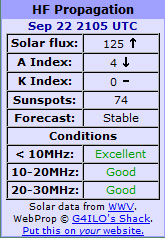
Conditions on LF appear to be excellent this evening and this is supported by the propagation forecast for this evening from G4ILO's website (see below) and on the RHS for the current conditions.
 |
| The weak trace seen by OH1LSQ on 500kHz this evening |

New weak signal modes for LF/MF
On the LF-reflector this evening comes news that Joe Taylor K1JT is thinking about the development of some new software for weak signal work on the lower bands. Although Joe has not yet had much chance to start coding development of the new modes, they should lead to even lower useable signal levels. JT8-2 is a couple of dB more sensitive than WSPR but JT8-30 (will take 30 mins to send a message) is likely to be around 12-14dB better. Modulation is a form of 8-FSK.
Just to put a measure on this, 12 dB weaker signals (using JT8-30) would mean considerably greater range could be achieved for a given ERP, or the power level of the TX could be 16 times lower for a given range (with WSPR), all things being equal.
Mode T/R TxT df tsym BW S/N*
(m) (s) (Hz) (s) (Hz) (dB)
------------------------------
How quickly K1JT can do the necessary coding will depend on his work load - he is a Nobel Prize winning physicist - but we are looking forward to the first release of this software in the coming months.Just to put a measure on this, 12 dB weaker signals (using JT8-30) would mean considerably greater range could be achieved for a given ERP, or the power level of the TX could be 16 times lower for a given range (with WSPR), all things being equal.
500kHz REAL DX with the new transverter
 |
| DX reports on 500kHz WSPR this evening using the new 10W transverter |
 |
| 500kHz WSPR reports map |
For details of my 472/500kHz transverter see https://sites.google.com/site/
QRPtransceiver.com website
 |
| http://www.qrptransceiver.com/website |
21 Sept 2012
GPS tracking?
Some help needed......
When out in the field locally receiving my VLF and LF test transmissions from home, it would be very helpful to be able to plot signal strength against location. For example, if doing a drive test, with an E-field probe antenna on the car feeding an LF RX and PC audio package such as Spectran, it would be excellent to be able to plot a map or database showing field strength and location. Now I have to confess I haven't a clue where to start! My knowledge of GPS is almost zero and my PC skills are limited to MS Word and simple spreadsheets in Excel (some years ago). So, if anyone knows of a SIMPLE way of achieving this goal please let me know.
On a related subject, what is the best, low cost, pocket GPS tracker that would record a walk (distance, track taken, times) and allow this to be plotted on a map when one gets home?
10m Simple Sideband (DSB) Transceiver
Regular readers of this blog will recall that about a year ago I started breadboarding a simple DSB speech transceiver for 10m. Having had great success with the WISPY 10m WSPR transceiver, I now have a very simple design for the TX part of such a DSB speech transceiver (just need to add an audio preamp/clipper/filter), so I am beginning to get ideas together for this project again. A power of around 1W pep (DSB) equivalent to 500mW pep SSB is the minimum I think. On RX a single balanced diode mixer (or a double balanced mixer such as an ADE-1 or SBL1) should be fine. For the VFO, I am thinking of a mixer/VFO with a tuning range of 28.4-28.6MHz. The RX audio design from WISPY works well but it will need another audio stage to drive headphones.
I want to have another go at a 136kHz transverter (based on my latest architecture), more non-line-of-sight (NLOS) optical comms, E-field probes, more earth mode comms, WSPR beacons for other bands, etc etc...
My problem is I've too many ideas in my head and not enough hours in the day to try them all out. What I need is a spare, free, design team (!) to take these ideas forward whilst I get on with other things, like looking after the grandchildren, gardening, maintaining the house, eating and sleeping etc. Since retiring 4 years ago I have no idea why I've no spare time!
20 Sept 2012
500kHz WSPR - 990km already tonight
This map shows people who have copied my 500kHz WSPR signal (using the new transverter) up to 11.20pm tonight. Best DX report so far is DL4RAJ at 990km from near the Czech border who gave me an astounding +5dB S/N report, a signal level good enough for a CW QSO.


472/500kHz transverter FINISHED


| The lastest transverter schematic (there may be value errors) |
 |
| WSPR reports 20.9.12 with the above transverter and 6m long antenna |
 |
| The desktop 472/500kHz station, ATU (don't laugh!) and antenna current meter |
18 Sept 2012
Japan Ham Fair 2012
http://onjapan.net/2012/hamfair/icom-kenwood-yaesu.html
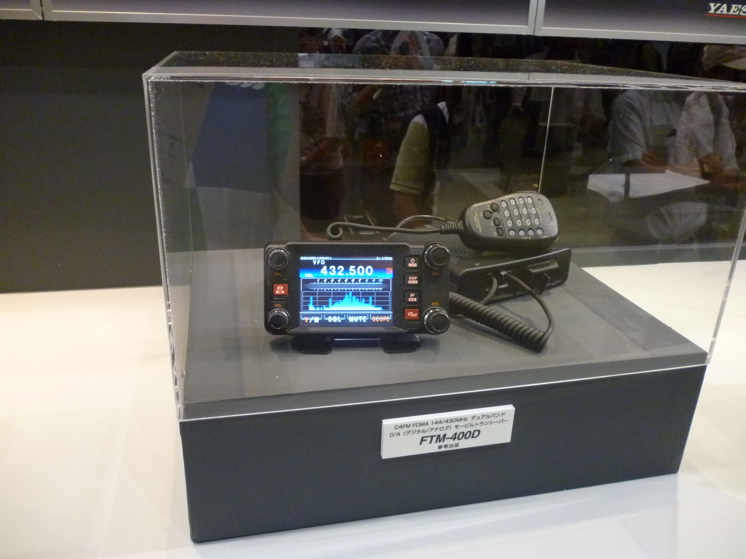
 The recent Japanese ham fair in Tokyo showcased the latest products about to hit the market in the coming months. Included was the IC-7100 all-mode, all band (including 4m) 100W mobile. What was not there was the long awaited FT-817 replacement. A product I have not seen mentioned yet is the Yaesu FTM-400D digital VHF/UHF radio. I don't think this is a D-star radio, so what form of digital modulation does it use? Is this a Japan only product?
WSPR for the iPod Touch
 Like many these days, I've an Apple iPod Touch and use it every day for web browsing. When watching the TV or reading the paper it is handy to be able to check my WSPR spots with a quick look at the iPod Touch.
 The Apple iPhone, iPad and iPod Touch do not have that many amateur radio apps. There are a few very useful ones like an audio spectrum analyser, an oscilloscope, Echolink and a repeater database, but what I would really like is a full WSPR interface for the iPod Touch. Does anyone know if such an app has/is being developed for Apple or Android products? Even Apple OS PCs seem to be less well catered for with regard to amateur radio software.
Subscribe to:
Posts (Atom)


