16 Mar 2013

24 hours with 1mW output on 40m

Well, that was fun: a 24 hour period with my WSPR beacon running at just 1mW RF output on 40m into the Par 10/20/40 antenna at just 5m up in the garden and yet still plenty of reports from around western Europe. Best DX reports were from F6HTL (737km) and F1ING (581km) with reports from G, PA, and F.  I shall now have a try at the same power level on 10m or 20m and see how it goes. It was interesting that there were few reports last evening and overnight on 40m, possibly because my 1mW signal was being crowded out by others running "high" power like 1-2W, HI.
Some of the reports with 1mW on 40m WSPR
A WSPR beacon TX at the 1-5mW power level is feasible with just one transistor and a single balanced diode mixer and may be one of my next "just for fun" projects.

UPDATE 1700z: on 20m WSPR with 1mW output I managed just one report this afternoon from F1JRC/2 at 971km.


15 Mar 2013

Chinese FT817 a step closer?

Steve G1KQH has alerted me to a new Chinese HF SSB/CW transceiver kit called the KightKit KR-10 that retails in the USA for $259.95  Although this is a kit, it is available ready made for just $30 more. That is less than $300 for a built HF QRP rig.

The rig doesn't look very pretty, in my view, and I/ve no idea about its availability in Europe including the UK.


The spec is:


  • RX frequency range: 0.1 ~ 30MHz
  • TX frequency range: 0.1 ~ 30MHz
  • Operating Mode: SSB / CW
  • Receiving sensitivity: better than 0.45uV,
  • RF output power: ≥ 4.5W
  • Frequency stability: better than 0.5ppm
  • Operating voltage: 12.0 ~ 14.0V DC
  • RX Standby Current: 0.5A
  • TX current: 1.5A Max
  • Dimensions: 97 x 40 x 155 (mm)
See http://www.kightradio.com/X1M-QRP-SSBCW-Transceiver-Kit_p_305.html for more details.

Now, there are clearly signs that the Chinese are coming up fast on the HF QRP transceiver front. It surely cannot be long before a Chinese company launches an FT817 competitor. They have a tall order to exceed its spec but they've had 13 years to dissect and analyse the Yaesu radio.  

1mW (0dBm) TX on 40m WSPR

Just for fun I'm having a go at QRPp WSPR on 40m. The set-up is the FT817 on 500mW going directly into a 26dB attenuator that feeds the Par 10/20/40 end-fed longwire antenna in the garden at around 5m above ground. So far, after about 10 minutes a few spots received: G3XVL at 61km being the best DX with reports also from G4IKZ and G4NRG.

13 Mar 2013

Amazing NLOS 481THz reception tonight!

This morning I realised that I was 2.5 degrees out in my aim last night with my optical beacon, so this evening I repeated the over-the-horizon optical test, moving instead to a new location fully in the beam at a distance of 4.8km. The difference was astounding! Last night I was struggling to copy the signal even with a long carrier. Tonight it would probably have been audible in 10wpm CW!
Excellent NLOS 481THz copy this evening
I ran QRSS3 tonight and was rewarded with signals 20dB over the noise in 0.34Hz bandwidth when beaming just above the horizon. At higher elevations the signal was weaker. With this strength I am very confident that with QRSS3 the signal should be copyable non line-of-sight (NLOS) out to at least 10km by forward scatter and possibly much further, even with my 1W LED running at 250mA in 100mm optics.  This was an excellent result and I am now confident the RX is working very well indeed.  Cloudbounce is another mode I have yet to properly exploit. The reception tonight was as a result of clear air scattering presumably from water droplets or dust particles.

This time I made recordings which are linked from my website. These can be played back through Spectran or Spectrum Lab software and further analysed. See https://sites.google.com/site/g3xbmqrp3/vuhf/optical/481thz-nlos .

Rapidly I am learning the absolute importance of accurate aim: 2.5 degrees out last night probably reduced the signal level by around 20dB. For serious tests over longer ranges a means of very accurately aligning the TX and RX is essential. Unlike with line-of-sight where the red dot can be seen by eye usually, NLOS requires careful alignment from map features.

12 Mar 2013

Successful over the horizon 481THz test at 4.6km

This evening, in the freezing cold, I attempted a non line-of-sight (NLOS) optical test using my beacon TX (1W 10mm LED at 250mA in 100mm optics) at home in the bedroom firing out through the double glazed bedroom window and my new improved receiver (SFH213 detector in 100mm optics) at a new test site 4.6km away towards Cambridge. The path is obstructed by rising ground some 10m above the TX and RX height around mid path.

481THz signal (top line) at 4.6km over the horizon tonight
This time, I used a lower TX subcarrier tone frequency of 572.3Hz and a continuous carrier transmission so that aiming would be easier (!) than with CW or QRSS3. I am pleased to report successful reception of the signal in 84mHz bandwidth using Spectran, but aim was extremely critical and the signal was not solid, probably because of  aiming issues and possibly changing sky conditions.

When I got home I checked the frequency to make absolutely sure that this was my carrier, which it was beyond any doubt. The signal was totally inaudible in the headphones and there was no sign whatsoever of the red beam in the sky. The most probable propagation was by scatter off dust particles in the atmosphere.

This was MUCH harder than I expected: I honestly expected to hear quite reasonable signals by ear, but as the plot shows, the signal was only just copyable in 84mHz. When I received my signal NLOS last year at 3.5km on a different path signals were 10dB over noise in a wider bandwidth on QRSS3.

At the moment I am still aiming the TX and RX as low as possible on the horizon, but I need to try greater elevations to see if this gives better to worse results over this sort of distance.

Another 6-10dB ERP from the Phlatlight LEDs (still to be fired up) would certainly help.

10 Mar 2013

Practical Wireless (April 2013)

G3XBM in New Zealand (Abel Tasman National Park) Feb 2009
For the second month in a row I have an article in Practical Wireless. This time it is one submitted several years ago describing my operation on 70cms FM when on holiday in New Zealand in 2009. New Zealand has an excellent internet-linked repeater network that links repeaters all across the country, so one can work from the very south of South Island all the way to the top of North Island and talk to anyone on this linked network.  I found this invaluable when on holiday.

Sadly the exchange rate is not as favourable now as in 2009, but New Zealand is a wonderful place for a once in a lifetime holiday, with very friendly and welcoming people.

If you get PW, I hope you enjoy the article.

Optimised 481THz receiver

As the weather was miserable here today, I decided to work on the K3PGP derived 481THz optical receiver this morning. I wanted to ensure it was working at maximum sensitivity with subcarrier tones around 100-1500Hz. With some adjustment of the coupling capacitors and the addition of an HF roll-off capacitor on the collector of T2, the sensitivity now appears to be excellent. My test is an AF modulated red LED on the ceiling of my building shack, in almost total darkness, with the test receiver (less any lenses) on the bench about 1.5m away. If the receiver is working credibly then the tone can be heard in the headphones when the LED is barely lit. In the case of this latest receiver I cannot even see the LED lit at all in a darkened room, yet the tone is audible in the receiver. When comparing this with my previous best optical receiver there is around (guess) 6dB more sensitivity. This design uses "blog standard" components: nothing selected for low noise, and not an IC in sight. I am now waiting for some decent weather - and no snow please - to test this on my NLOS test path.

9 Mar 2013

K3PGP receiver for 481THz

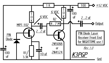
One of the simplest, yet highly sensitive, receivers for optical communications is one designed by John K3PGP. The G8CYW design in Practical Wireless in the March and April 2013 editions is based on this. This works really well in darkness, but is easily overloaded in any light. Many circuits are optimised for speech communications but this one works really well with digital modulation at very low frequencies where the detector sensitivity is highest.
http://k3pgp.org/Construction/Frontend/preamp.gif
Today I've been building a version and I am in the process of optimising it for subcarrier frequencies below 500Hz. I have added an extra transistor gain stage after the basic K3PGP design but want to see if lower noise FETs and transistors make a worthwhile improvement. When satisfied that it is working optimally I shall be trying this at the RX end of my over-the-horizon tests. I am quite excited about trying much lower frequencies in the next test using QRSS3 and continuous carrier.


10m WSPR today

Today I've been running either 50mW or 2W on 10m WSPR. 50mW was enough to get to 4X1RF but 2W was needed to be seen in Uraguay at 11127km using the Par-10/20/40 endfed antenna. The jury is still out on how performance on the 3 band antenna compares with the 10m halo, which is currently down pending a rebuild.

8 Mar 2013

Source of BRIGHT red LEDs

Some have asked me what LEDs I've been using so far for my optical experiments. Well, these are 10mm diameter "conventional" style LEDs from a source in Hong Kong. They are 1W devices capable of 280000mcd output and look like a normal LED on steroids in that they come in a standard looking clear package with 2 thick leads.

They are available via eBay at £9.30 for 10 off from Hi Tech LED World.  The supplier delivers promptly and with good packaging (and a nice collection of attractive stamps on the package). They also have a range of other devices available.

Use the link http://www.ebay.co.uk/itm/350347623711 .

As mentioned before, I also have some even more powerful LEDs called Phlatlights which are intended for overhead projectors. I've still to fire these up. These are about 10dB more powerful than the 1W LEDs, so are potentially dangerous.

Gaps in my knowledge

Sometimes I feel a complete fraud: people drop me emails and ask me questions and I am completely at a loss how to answer. The reason is there are an awful lot of things that I should know about that I don't. As an example, PIC programming: many of the things I want to do, like make a simple VLF frequency generator with FSK keying could probably be done very easily with a PIC, but I have never, ever, used a PIC and certainly never programmed one. There are whole areas of circuit design in which I'm very weak, for example digital logic, microprocessors etc.  Even my RF knowledge is frankly far from expert.  In my professional life I managed to get promoted into management roles where my "hands on" RF skills were not an embarrassment! You'd be surprised how many managers in RF jobs are not actually that hot at RF design.  Mind you, it helps to have a "jizz" (instinctive feel) for RF and I did (and still do) have this.

The reason I raise this is to give others hope. Even without knowing too much a lot can be done and we are never too old to learn new tricks. There are far too many things to know about to be experts in everything and the best we mortals can do is try our best in a limited area. This is why I concentrate on simple HF and low VHF QRP projects, optical and VLF work which I can get my head around. I'll leave the complex stuff to people far better than me.

http://uk.farnell.com/productimages/farnell/standard/1701537-40.jpg
At some point I may have a go at PIC programming but writing software was never my strong point. Neither was maths for that matter. Talking about PICs, if I wanted to have a go at PIC programming what do people recommend for going about it? What is the best (simple please) book and what is the best development kit on which to try out the programmed devices?

Rockmites

Some years ago I bought a Small Wonder Lab Rockmite-20 from QRPshop in Germany. As I didn't have a suitable antenna at the time, the project got shelved and the complete kit has been sitting, unbuilt, on my shelf. Now I have a Par-10/20/40 end fed antenna up covering the band I've no excuses. So, maybe next week in between other experiments I'll build it and try it on the air.  The reviews of the project on eHam.net are very good with a score of 4.9 out of 5 from 79 reviews. It is a clever design with a full keyer built in and using a couple of crystals with one as a front end filter to keep out the broadcast breakthrough.

Aiming high

This evening I caused a few curious looks on our road as I adjusted the optics on my latest 481THz beacon in the dark.  In order to carefully align the powerful red beam, it is important to ensure the cross hairs on the gun sight telescope used for aiming are precisely aligned with the tightly focused red beam.  I beamed onto the rear of a distant car and made some adjustments. As I was doing this, someone walked down the road with a dog and stood, puzzled, at why this car number plate was glowing red very brightly!  The beam was aiming slightly too high, but after adjustment is now precisely in the centre of the cross hairs, so next week, weather permitting, it will be time to try again at the NLOS test.

New 481THz QRSS3 beacon ready for action

Completed 481THz beacon electronics
This afternoon I finished off the electronics build of the new dual frequency optical beacon TX for 481THz (red light) over-the-horizon (NLOS) tests. In the end I opted for QRSS3 on a choice of 2 sub-carrier frequencies selected by toggle switch together with the option of a continuous sub-carrier transmission on either frequency to help beam alignment. I have not incorporated an FSK facility at present. All that remains is to align my sighting scope with the optics so that I can use this to help with aiming. Currently the beam appears off-centre in the spotting scope cross-hairs.

As I now have the option of a lower sub-carrier frequency, I need to revisit the improved RX to see if I can better optimise sensitivity at the lower frequency. Theoretically the detector should be several dB more sensitive at a lower sub-carrier frequency which should help with NLOS tests where signals are weak.

The beacon is powered by a 19.5V 4.5A ex-Dell laptop SMPSU, although I only need around 300-400mA with the current LED, which is exceedingly bright.  In the picture above you can see the BACK of the LED and that is pretty bright. At least with the PSU the whole beacon is self-contained.

7 Mar 2013

Progress on the new 481THz beacon TX

Today I made a start on the new optical QRSS3 beacon. This time, the circuit has some improvements: a continuous sub-carrier option and a choice of audio subcarrier frequency. Also, the frequencies are now derived from an HF crystal so stability will be excellent.

The part completed new 481THz QRSS3 beacon
The oscillator/divider is a 4060 IC and this is enabled by the output of a K1EL keyer IC programmed to send "XBM" in QRSS3.  The square wave output from the 4060 feeds the gate of an IRF510 FET which switches the 280000mcd, 10mm diameter, LED in 100mm optics.

A possible refinement will be to pull the crystal using the keyer output signal so that I have a continuous carrier but FSK keyed. This would mean I'd always have a signal to aim at, but with FSK QRSS3 CW on it. I'm not sure how much pull I'd get after dividing down if I just changed one of the capacitors loading the crystal. I shall have to experiment and see. Even as little as 5Hz would be enough, but that would need 50kHz shift at crystal frequency! A better way may be to key the frequency out of the 4060, so mark is, say 550Hz and space 1100Hz or vice versa. Plenty to try tomorrow.

6 Mar 2013

Frustrating day at both ends of the spectrum

Today I tried two experiments. Firstly a continuation of my tests with the loop and E-field probe out in the fens on 8.977kHz and then tonight, another over-the-horizon test on 481THz.

Failure 1 at VLF: whereas in the past I've had a decent signal at my test site at Tubney Fen 3.5km from home on the loop antenna on 8.977kHz, today I could copy nothing. There was some strong interference and I thought that may have been the problem, so I moved on to a second test site 5km away where again I usually get a good signal. Again nothing. In the past this second site has given me signals so strong that I could copy 10wpm CW from home on 1kHz by earth mode. Now around the village and in nearby Swaffham Prior the signal levels were (as far as I can recall) similar to past levels, so what has changed? One theory is that the wet winter has saturated the fenland soil so conductivity is much higher, resulting in much higher attenuation at VLF.  Another possibility is some utility has changed - a change of pipe type or a re-routing of an electricity cable? My TX and RX equipment is largely the same as in previous tests.

Optical QRM on the 820Hz sub-carrier frequency
Failure 2 at 481THz: I tried a third attempt at my over-the-horizon QRSS3 reception of my signal on a 820Hz sub-carrier. This has been successful in the past. The 100mm lens TX was carefully aligned just to the right of our local windmill on "the hill" and I traveled to what should have been a direct line path (but over the horizon so the signal has to be scattered) about 3.5km away. Optical conditions looked good with clear visibility of street lights in Burwell. Well, I am pretty certain that I was able to hear my signal by ear in the headphones keying away slowly, but because of a lead failure (later fixed) and then a strong interfering signal very close to the 820Hz sub-carrier, I failed to see my signal with Spectran and make a screen capture. I think this QRM signal is related to new street lighting as panning the horizon brought up this interference on most street lights at around 3km range. The solution will be to choose a different sub-carrier tone frequency. BTW, it is fun to hear the strobe lights from aircraft: these are very strong and can be copied well off the direct path by scattering.

My next immediate priority is to change the optical beacon TX so that I can use a range of different sub-carrier frequencies all derived from an HF crystal divided down with a 4060 divider. This will also allow me to run a continuous signal which will help with alignment and I can avoid QRM by moving the HF crystal frequency if needed. I could also arrange DFCW modulation by FSK keying the HF crystal: this will allow a continuous signal for audible alignment yet be detectable with software packages like Spectran in QRSS3.

As regards the VLF earth-mode tests, for now I am going to draw these to a halt and will try again in a month or so when I hope the fen soil conductivity has reduced. If things are unchanged then I suspect that something in the utilities metalwork out in the fens has (permanently) changed.

5 Mar 2013

Projects update

It is some time since I summarised my projects list and progress. This is the current "ideas list" for the coming months. As we are in the middle of a house renovation/move project over the next 3-6 months it is quite likely that my amateur building work will have to go slow.
  • VLF earth-mode - optimising the E-field probe and loop antennas for mobile coverage tests
  • 481THz Optical NLOS tests - testing new RX and then trying the 10dB higher powered PhlatLED TX and seeing how far over the horizon I can reach.
  • WISPY 10m WSPR beacon - combining the TX and RX boards into a full WSPR/PSK31 transceiver. Separate modules made and tested but yet to combine.
  • Tenbox - I still need to finish either the AM transceiver or modify the design to a DSB transceiver.
  • 2m horizontal omni antenna - I need a simple horizontally polarised omni antenna for the new QTH. I'm tempted to organise a pair of stacked big-wheels with around 5dBd gain.
  • Simple test equipment for the shack at the new QTH - I want to build a number of pieces of simple test gear such as a frequency counter and simple spectrum analyser 
  • Rebuild of the 10m Homebase-10 halo - the wooden frame structure is showing signs of age, so a fibre-glass support may be less visible and more durable 
Now, knowing the way things work with me, I 'll wake up one morning and think of something completely different to work on. That is the fun of simple homebrew amateur radio experimentation: no-one tells you what to do, unlike when at work, and each day is one filled with opportunities.

Double or single peak for cycle 24?

At the moment the jury is still out on this. We've seen activity slide since the peak around Nov 2011 but there may be signs that the trend is upwards again leading to a second peak as has happened in a few recent sunspot cycles. This NASA video gives some insight into the thinking.

More analysis with Spectrum Lab software

Spectran is a very easy package to use but it has its limitations when analysing weak audio signals. A more powerful package is DL4YHF's  Spectrum Laboratory which is an extremely powerful piece of software. The problem is that if I've not used it for months it takes me hours to remember how to drive it. A secret is to store ".usr" configuration files so one can go back instantly to a set of settings e.g. a given frequency to analyse with a specified bandpass filter and bandwidth.
Faint line at 8.9775kHz visible at greater range (43mHz bandwidth)
Anyway, to cut a long story, this evening I set up some config files to allow me to look again at the recordings of my 8.9775kHz VLF earth-mode signals made during recent drive around tests locally. Although the original analysis was done at 180mHz bandwidth I can now replay the recordings and look in bandwidths down to 34mHz. What happens then is that signals present but too weak to see now appear above the noise floor as a faint line. The net result is that the signals can be detected in some of the "in between" locations that were not apparent from the 180mHz (wider!) bandwidth analysis.

I intend to use Spectrum Laboratory and narrow bandwidths for the over-the-horizon 481THz optical tests if Spectran proves not up to the job. However, when bandwidths are very narrow there is a time-lag before the trace appears on the screen. This is less than ideal when trying to align weak optical signals with beamwidths measured in a degree or less. What is needed is an accurate beam heading and then allow the trace to build on the screen. I don't have enough experience yet to know how much beamwidth spread a cloud or free space dust scattered optical signal gets. When looking for G4HJW's signal over the horizon in clear skies last year the alignment was quite critical, but his signal was audible in headphones so the optics could be peaked by ear before analysing with Spectran or Spectrum Lab. I had more luck with my own QRSS3 signal over the horizon on a shorter path, managing to align by eye on visible landmarks enough to see the trace on the PC and then peak it.

Mobile 8.977kHz VLF loop tests started

Today I started to do my tests on 8.977kHz using my 5W earth mode transmitter at home but using a mobile loop antenna on the car connected to my PC via a tuned preamp. The idea is to be able to drive around and measure signal levels with Spectran software whilst actually on the move.
30t 80cm loop mounted behind the car
The loop was mounted behind the car in such a way that it would detect any ground propagated signals. The loop is about 10cm off the ground.

A drive test to Swaffham Bulbeck was carried out and signals were detected more or less continuously out to 3.5km from home before they disappeared in the noise. Bandwidth used was 0.18Hz with a continuous carrier. Although coverage was as I anticipated, signal levels were not as great as when the loop was actually laid directly on the ground. At one of my usual test sites 3.5km out in the fens there was no copy with this loop arrangement yet there was a decent signal copied with the loop on the ground a few days earlier. I need to do some direct comparisons between the loop on the ground, the loop mobile mounted 10cm above the ground and with the E-field probe on the car roof. Initial indications are that the difference between the EFP and the mobile loop is probably no more that 5-6dB.
Signal received with Spectran and the mobile loop


Revised UK Frequency Allocation Chart

From the OFCOM email newsletter today:
UK Frequency Allocation Table

Ofcom has published a revised UK Frequency Allocation Table. This details how various frequency bands are used in the UK, and which bodies are responsible for planning and managing them – including frequencies assigned to individual users or installations at particular locations. It also shows the internationally agreed spectrum allocations of the International Telecommunication Union. 
The table shows frequencies below 8.3kHz are unallocated in the UK but there are some footnotes in the ITU frequency allocation table that require administrations to ensure no harmful interference to services above 9kHz and to notify other administrations about research below 9kHz.

My understanding is therefore that below 8.3kHz the UK administration "does not care" what happens as long as interference to allocated services is avoided. This is my interpretation and not a legal statement.

2 Mar 2013

VLF earth-mode mystery deepens

This afternoon I did a larger coverage test with 5W  8.977kHz earth-mode, driving in several directions locally in the car with the roof mag-mounted E-field probe RX antenna and with a PC in the car monitoring the signal. I drove for several kilometres in different directions recording where the signal could, and could not, be copied. The best reception distance with the E-field probe was 3.2km.

The map shows the results. Yellow shows where I drove and red shows where there was signal present and recorded on Spectran. I have recordings of the whole trip which I will more carefully analyse later.
5W 8.977kHz earth-mode coverage using EFP RX antenna
The interesting thing is that the signal could be copied in 4 local villages (Burwell, Reach, Exning and Swaffham Prior) but there was almost zero coverage once outside of these villages. This is NOT the case when looking with a magnetic loop RX antenna, where the signal can be copied more extensively in the rural areas at even greater distances.

It would appear that the E-field signal needs to be strong above ground to be copied with the EFP and this only happens where there are buildings i.e. in the villages. It suggests I'm detecting the signal from cables or pipes in houses.In more rural areas the signal is weaker above ground and not detected, at least not with 5W TX.

1 Mar 2013

Mobile on 8.97kHz VLF

Route taken from A to F (about 4km)
Today I did a fascinating experiment on 8.977kHz VLF using my 5W earth mode transmitter and a mag-mounted E-field probe and laptop running Spectran in the car. Basically I did a "drive around" test to see where the signal could and could not be copied.
Signal strength on 4km run between 2 villages
A continuous carrier was transmitted and I continuously monitored the received signal in the car. The drive was from the middle of the next village (Swaffham Prior), out through to the main road, then back along the main road to Burwell, around part of the village and then back home to the TX location. The signal was visible in Swaffham Prior at 5-10dB S/N, then disappears and returns on approaching Burwell where it is up to 40dB/S/N in 0.18Hz bandwidth. Within Burwell it is almost solid copy. The red timing ticks are every 30 seconds.

What I am detecting (I think) is the local E-field from the VLF signal in the ground, no doubt aided by local utilities. What puzzles me is why there is NO copy in between the 2 villages when there are, I think, pipes and cables in the road.

In the coming days this test is worth repeating locally in other directions and further afield. Fascinating to think a 5W VLF signal injected into the ground can be copied on a 19 inch whip on the car roof like this.

28 Feb 2013

Another approach to 472kHz WSPR

An old work colleague Richard G4KPX has been doing more experiments with indoor loop antennas. Recently he has been using an indoor loop for 472kHz with an ERP of around 1mW. I just checked the WSPR database and see he has achieved some amazingly good results with 49 unique spots with best report from Sweden at over 1300km! Well done Richard.
G4KPX's WSPR results over 500km with just an indoor loop TX antenna

Optical NLOS test - next time pack everything!

This evening I set off to my Landwade location where I hoped to check the non line-of-sight (NLOS) signal level from my 481THz, red LED, QRSS3 beacon TXing from home. This time I'd carefully aligned the TX and adjusted the RX optical alignment in daylight, so everything should have been spot on.

481THz RX with iPod Touch 4g running SpectrumView
Then I realised I'd left a vital lead at home that allowed me to connect the optical RX to the laptop. Next time I need a checklist as it is a 10 mile round trip to the test site.

Instead, I tried to copy the signal using the optical RX fed into my iPod Touch with SpectrumView software, but the bandwidth was too wide to allow me to find the weak signal. I hope to repeat the test in the next week (with the laptop and Spectran set to 0.34Hz bandwidth), but this time with EVERYTHING packed for the test.

I was very annoyed with myself for forgetting this audio lead as it prevented a meaningful test being done. I also need to find a different NLOS test site that is less far to drive to but still at about the same distance (3.6km).

The limitations of my cheap tripod are also apparent: I need a much sturdier one that has a compass attached and much smoother pan and tilt.

8.97kHz earth-mode tests with mag-mounted E-field probe

Today I started some tests at 8.97kHz with my mag-mounted E-field probe (EFP) on the car roof. As usual, the transmitter was my 5W QRSS3 beacon feeding the 20m spaced earth-electrode antenna in the garden.

The logical starting point was to drive to my usual "strong" test site 1.6km from home and compare signal levels on the usual 80cm square RX loop with that on the EFP.  For reasons I have yet to understand the signal was NOT copied, even on the loop! What I did see was what looked like an FSK telemetry signal, possibly from overhead power lines close to 8.97kHz. I've never seen this before. Anyone know what it is?

8.97kHz 5W earth-mode signal at 0.4km on E-field probe
I then drove to my new QTH (due to be occupied in about 4-5 months time) which is 0.4km from the TX and sat in the car in the drive with the iPod Touch 4g running SpectrumView software connected to the EFP. The antenna was a short 19 inch whip. Signals were copied quite well (see photo showing "3" from my callsign). The bandwidth on SpectrumView cannot be narrowed enough to optimally receive QRSS3 and results would be better with the PC set to 0.34Hz bandwidth.

Tomorrow I'll have to find out why I couldn't see my earth-mode signal at the usual test site on either antenna. I'm also going to do some /M reception at 8.97kHz using the E-field probe and laptop with Spectran set to 0.34Hz or 0.17Hz bandwidth. With a continuous signal I'll be able to log the signal level as I drive around the village and nearby.

27 Feb 2013

What IS amateur radio?

This is a question I keep asking myself. It clearly means different things to different people, but I am saddened by the trend to cheque book amateur radio.

In its early days the hobby was clearly about experimental radio: making receivers and transmitters that communicated over short distances, with many/most of the parts being hand-made, even down to the variable "condensers". Over the years this has changed for many (most?) amateurs and now one could be forgiven for thinking all that matters is how expensive ones new HF radio or antenna is, so one can boast about how wonderful ones station is to others on HF.

I was struck by the cost of the hobby, for some, again tonight when visiting http://www.bigskyspaces.com/w7gj/vhf.htm and looking at the massive and very expensive antenna farm at W7GI.  Now this 144MHz antenna, like many, antenna arrays at this amateur's QTH is aimed at reliable EME operation where large antenna gains help. But what I see is 16 very expensive antennas plus an equally expensive support structure, expensive coax and an expensive mast. This is just one antenna for one band. He has another very big array for 50MHz too, plus no doubt a shack full of expensive radios and linears. The rotator to turn this lot will be a very large device indeed.  Yes, successful EME operation needs big antennas and high power, but honestly is this AMATEUR radio still or semi-commercial experimentation?

I can understand why an amateur may want one 100W commercial radio as the "mainstay" radio for the shack, but I see many shacks loaded to the gunnels with very expensive radios that must have cost their owners well over £10k and in some cases well over £20k.  It amazes me how much money some amateurs must invest in their hobby. I had a decent job and a decent salary when I worked, but there is no way I, personally, could justify this sort of expense on my hobby. It's a personal view and I do not want to preach to others on how to enjoy their hobby, but I am fascinated that spending lots of money on radios seems to be the norm.

Are any readers prepared to share (in the comments) how much they spend, on average, a year on their hobby? £10, £100, £1000, £10k, £20k?  Just for the record, I reckon on about £2 a week (a couple of new HF transceivers over 12 years plus the odd accessory and components).  It is possible to really enjoy the hobby and spend less than the cost of a coffee every week.

My question is, what IS amateur radio?

472kHz earth-electrode WSPRing this evening

The 472kHz WSPR beacon has been running this evening using the 20m spaced earth electrode antenna described in my March 2013 RadCom article. A reminder that there is NOTHING in the air at all, just the wires along the grass to the earth rods.

Quite a few reports received and given already.
472kHz unique WSPR reports received so far tonight
The same earth electrode antenna will be used at the TX end of my VLF test with the mag-mount E-field probe RX tomorrow morning.

Stake out on 481THz

481THz RX on tripod with optics.
In the daylight today I went to the RX site used in last night's unsuccessful over-the-horizon (NLOS) optical beaconing test. I've now marked out on the ground (with sticks and stones!) the exact direction to aim my RX in when I return for a second try, hopefully tomorrow night.

Yesterday it was so gloomy that I could hardly work out where to aim, so this now means I can be within a few degrees accuracy on initial set-up. I've also adjusted the aim of the TX beacon optics. Visibility for Thursday night is forecast to be "very good" with cloud cover according to my Met Office app, so let's hope it works OK tomorrow.

The RX and 100mm optics are shown above. Note that the upper tripod extension (below the tilt arm) is rarely extended as the whole thing is then too wobbly. I need a more sturdy tripod. Also, the low cost gunsight scope (bought for just a few pounds off eBay) is of little use at night (too little light) but very useful in daylight.

Mag-mount E-field probe on 8.97kHz

Just as an experiment, this afternoon I modified my mag-mounted FET drain tuned E-field probe to work on 8.97kHz. The last time I rigged an E-field probe on 8.97kHz and went looking for my earth-mode signal results were very disappointing wih just a couple of places within 2km radius where the 5W beacon was copied, but tomorrow morning I'll see how well (or not) it works. To tune the FET drain to 8.97kHz I just substituted the 137kHz tuned circuit with an 83mH Toko potted coil in parallel with 4n7. Tuning is reasonably sharp. Whether the car grounding will make a big difference we'll see in the morning.

26 Feb 2013

Eddystone User Group

If, like me, you owned an Eddystone communications receiver at some point in the past then you may like to look at the Eddystone User Group pages. Here you will find lots of data on old receivers, links to data sheets and service manuals and a lot else too.

In my case I owned a Mk 1 EC10 receiver similar to the one shown here. This was state of the art in the late 1960s when it sold for £48. By modern standards it is a pretty rubbish receiver.

481THz over the horizon test: no success tonight

Weather this evening was not suitable for the tests, although I did try. I set up the QRSS3 beacon pointing out of my bedroom window using the local windmill as the aiming point. This is on the top of our small hill which rises about 15m. I then drove to a spot 3.6km away over the hill to look for the signal with my sensitive RX and 100mm optics using Spectran to display the trace. Unfortunately this time the slight drizzle and murk was just too bad and no signal was copied, although I've had good results in the past at a very similar spot.

In daylight I need to recheck my beam alignment at the RX location as it was sufficiently murky to not see the local landmarks used to help aim the RX last time. Despite panning across 45 degrees of aim nothing at all was copied of my signal. I shall repeat the test in better optical conditions.

For those interested, the 1W 10mm diodes are available from http://www.ebay.co.uk/itm/350347623711.  You get 10 pieces for £9.26 with free postage and they are very BRIGHT.

481THz optical tests over the horizon tonight

This evening I am doing my first "over-the-horizon" optical test this year. The main aim is to check performance with the new receiver and to see how I get on using the iPod Touch 4g running SpectrumView software as the way of seeing the QRSS3 signal. I shall also be taking the laptop running Argo or Spectran.
Latest receiver that seems more sensitive than my older RX
The receiver circuit is the one in Practical Wireless this month by Stuart Wisher G8CYW. This is simple but works well in darkness. I've added an interface to the iPod Touch 4g (a capacitor and a resistor needed to enable the external mic input) and changed the coupling caps and op-amp gain. Using just MPF102 and 2N3904 devices the results look good. The low noise op-amp may be overkill unless one uses super low noise FET and transistor stages too.

After the tests I'll post results in the blog.

40m WSPR with 50mW - best DX spot 6505km

Reports received with 50mW on 40m
Overnight I've been WSPRing with 50mW output on 40m using the Par 10/20/40 end-fed antenna down the garden.  The FT817 set to 500mW directly feeds a Telonic 10dB rotary attenuator set to 10dB attenuation, so no chance of radiation from a coax cable. The antenna is only about 15m long and just 5m average height above the ground. Results (see above) have been very pleasing with best DX report from the USA - K9AN at 6505km.

25 Feb 2013

Bug keys

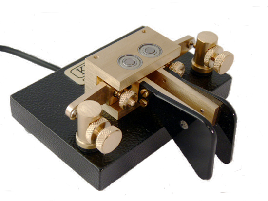
Kent twin paddle key
Although not a frequent or very good CW operator, I do like to try QRP CW from time to time, usually with a straight key I've had for over 40 years. With rubber stamp QSOs on HF I can usually manage OK. The problem comes when people ragchew and I lose concentration!

Some years ago I bought a beautifully made Kent paddle key but I've hardly ever used it because I kept making mistakes. So, today I dug it out and decided to persevere with it on 40m CW. I managed a nice (unexpected) 2-way QRP QSO with Rick DK4QK who, despite my sending, managed to copy everything. Later I worked DM0E on 2-way QRP as well, using the bug. Like all things, good CW comes with practice and use. Using a paddle key should allow me to send better and faster CW with a little bit more practice on my part.

So, if you hear me calling CQ on 40, 20 or 10m in the coming days on CW, and there are plenty of mistakes and extra dots, then you'll know who it is.

20m WSPR

As the weather is totally miserable I decided to sit by the fire today instead of doing any amateur radio building. In the comfort of the lounge I am watching the spots being sent and received with 2W to the Par 10/20/40 end-fed antenna on 20m WSPR. 20m is not a band I use much, preferring 10m, although conditions on 10m have nothing like matched the conditions close to past sunspot maxima.
Some decent range spots (TX and RX) despite lackluster conditions on 20m

Exchange rate changes and ham rigs

In recent weeks the pound sterling has declined quite a bit against the US dollar and the euro. Against the dollar it has fallen from around 1.62 dollars to the pound to around 1.51 to the pound. This makes purchases of rigs like the KX3 even more expensive here in the UK.

On the other hand, the yen has weakened from 125 to the pound to around 142 to the pound.  Expect some discounting of Japanese rigs in the UK incoming months.  The latest yen exchange rate suggests a new FT817ND should be less than £500 again soon.

Which major dealer will be really public spirited and pass on their savings to us the amateur radio public?  Martin Lynch or Waters and Stanton?

24 Feb 2013

A PSK31 QSO

Well, the little grandchildren have gone back home to mum and dad so the house is very quiet (and tidy!) again. This afternoon I decided to do a bit of QRP on 20m as a change. First a nice 2-way QRP QSO with Emi IZ4RDX who was running 5W (me 2.5W) and then a PSK31 QSO with Luis EA3UV. Neither contacts were great DX, but fun.  For the PSK31 QSO I decided NOT to use those pre-prepared messages and instead just keyed in what I wanted to say as the QSO went along. It felt like a real QSO, which was nice.

Tomorrow I hope to get back to the optical beacon work, but after 4 days of (lovely) little grandchildren this afternoon I just needed to "chill" as they say.  The plan is to build a beacon TX that will allow a range of subcarriers and also continuous subcarrier transmission as well as CW and QRSS beacon messages. I hope to get out "over the horizon" looking for the signal later in the week. Watch this space - literally if you are nearby, HI.

22 Feb 2013

PSK31 mode

Julian G4ILO mentions his enjoyment of PSK31 on HF on his blog today.  Although I've had a fair few QSOs and some good DX with this mode over the years, I'm not a great fan of it.

Although Julian rightly says it is a very good mode that well complements CW and SSB, and it is certainly true that the PSK31 part of the bands are often busy when CW and SSB signals are absent, to me QSOs feel too formalised with exchanges that follow fairly standard formulae. Too often it feels like a PC talking to a PC. Maybe I should try next time to avoid using these pre-programmed messages and go for a normal free-form keyboard "chat" instead.

It's a while since I've tried PSK31 on HF. Maybe next week when the grandchildren go home I'll give it another go.

The ARRL reports that Varicode, as used in PSK31, has now been officially recognised by the ITU. See http://www.arrl.org/news/amateur-created-varicode-adopted-as-itu-recommendation .

More VLF activity from Germany

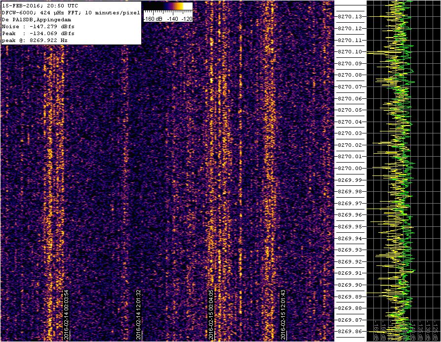
DJ8WX has been experimenting with a new GPS locked frequency source and is trying to put a signal out on 8.9700000kHz.  The signal has been received strongly by several stations including Paul Nicholson in Todmorden and at PA1SDB. This is the signal at PA1SDB over the last few days. Note the timescale on Peter's grabber covers several DAYS. Such is the world of amateur VLF!
Signal from DJ8WX now on 8.970000kHz (was 8.970022kHz)