25 Jun 2010

German VLF earth mode test: 5.2 km on 8.97 kHz

Stefan DK7FC has been doing some experiments with around 50W to a 300m spaced grounded earth electrode "antenna"  in a remote location in Germany. Today his experiments were successful with his transmission of 30 minutes clearly received on his E-field probe receiver and grabber located in the city some 5.2km away.  See the report on his experiments at  http://www.iup.uni-heidelberg.de/schaefer_vlf/VLF_5km_with_an_earth_antenna.pdf . Stefan can improve the electrode arrangement and increase current into the ground as well as run up to 500W. He's hoping to see the signal on the DF6NM VLF grabber located 174km away. If successful, this would be the first reported amateur radiated VLF DX using earth electrode antennas.

24 Jun 2010

VLF Earth Mode: 5.25km DX today with 4W

This evening I repeated my visit out in the fens with my loop seeing how far I could copy my 4W 838Hz beacon. After getting good QRSS3 copy at the same location 5.1km out as 2 evenings ago, I then tried going further out along the same fenland drove road. Although I managed to copy the signal at 5.25km this evening, no copy was achieved at any greater range despite travelling along several different lanes in many different directions. I'd like to know what it is in the roads that is helping - I assume water pipes, but it could be gas pipes or buried cables. What is clear now is that without these, the signal is absent more than 0.5km from home. This time I tried looking for the signal in far more places about 4-6km to the north of the village, but there was no trace of signal in this direction. Best directions are west (fenland peat) and south (chalk uplands). I've still to test to the east.

Another future test will be to try receiving the signal with a second pair of earth electrodes instead of the loop at some distance from home as one might expect stronger signals. This test will have to wait until the weekend though. If similar to results close to home, the 50Hz noise will be much worse though and this may prevent reception unless very quiet spots can be found.

Another beautiful QRP transceiver from AA1TJ

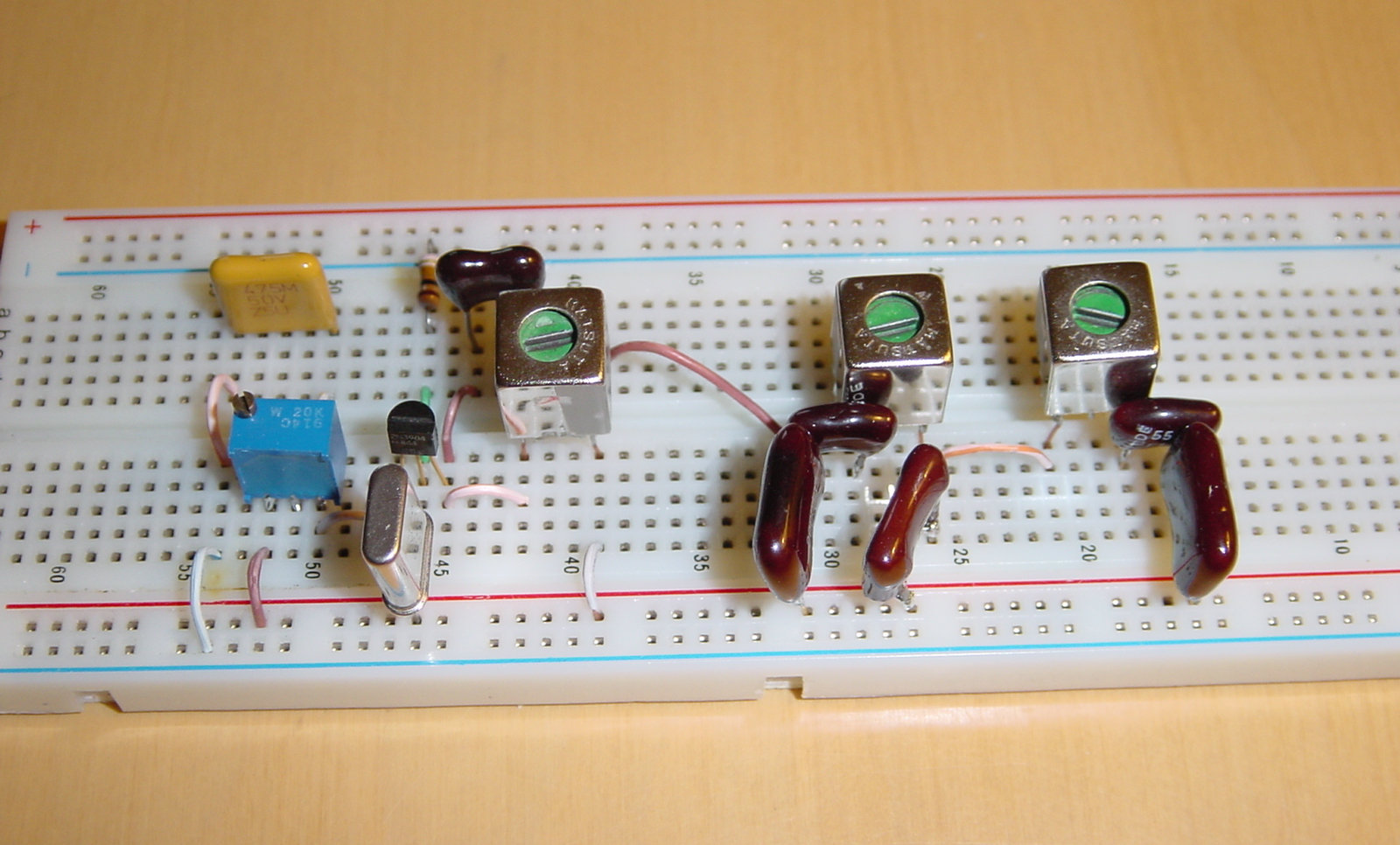
Menos es MAS is another fine QRP transceiver design from Mike Rainey AA1TJ. This really is about as simple as an HF transceiver gets with reasonable performance and QSOs in his log to prove it.  I like Mike's technique of using a development board to knock circuits together. This approach is fine for lower HF bands.

23 Jun 2010

Earth Mode DX map

This map shows the places round and about my QTH in Burwell (JO02DG) where I was, or was not, able to receive my 4W 838Hz earth mode signal in tests on June 21 and 22nd. Red dots here show attempts that failed, i.e. no signals detected, and green dots show where signals were successfully received and recorded. Best DX was 5.1km, but further is certainly achievable on QRRS3 with "utilities assisted" earth mode i.e. where ground coupling is enhanced by buried pipes and cables. Best DX with 4W into the 20m spaced earth electrodes using purely induction seems to be around 0.5km.

136kHz using the earth electrode "antenna"

This evening I was able to copy G3XIZ on 136.5kHz CW at 559 using my deaf (at 136kHz) FT817 fed from my 20m base earth electrode "antenna" used on VLF. I've made a recording and emailed it to Chris who is 46km away from me. Later this year I hope to transmit QRSS or CW on 136kHz, but the antenna needs some thought as I don't have much space.

22 Jun 2010

Earth mode VLF DX now 5.1kms

Today I managed to copy my 4W earth mode 838Hz signal at a range of 5.1km. QRSS signals were so strong that I was able to copy by ear my 10wpm CW beacon too! To copy the 10wpm signal I needed Spectran running with narrow bandpass filters. Without the filtering, all that could be copied was 50Hz noise.  At this range the signal level is definitely being helped by conduction through pipes in the roads and the main propagation is not by induction. Lots more information as well as screen shots and recordings on my sub-9kHz webpage.

21 Jun 2010

VLF Earth Mode: 3.6km DX today with 4W

My earth mode VLF DX increased to 3.6km today using QRSS3 and a PC running Spectran. TX was 4W into 20m separated electrodes in the ground. TX frequency was 838Hz. The 80cm loop and preamp receiver were set up in several places well out of the village in several directions and results well exceeded my expectations. Lots of information on my earth mode webpage including screen shots and sound recordings made using Spectran when out in the field.
This screenshot was from the roadside 2.5km south of the QTH. Signals were so strong (30dB S/N) that the signal was audible when Spectran's BPF in circuit (lots of 50Hz hum without).

20 Jun 2010

More 500kHz weirdness

Today I experimented some more with 500kHz WSPR using earth electrode pair arrangements rather than conventional antennas. In the end I was still getting reports from 210km away when using around 100uW ERP (maybe less) from a loop consisting of an earth rod outside the back door connected to about 7m of wire back to the bedroom with the other connection going to the central heating radiator. Why this works I have no idea! My latest theory is that this small loop is acting as a coupling loop to local overhead phone wires. I can't see otherwise how this "non-antenna" can otherwise work.

19 Jun 2010

Stable audio frequency tone generation (for VLF QRSS)

Next week I want to try QRSS3 with my earth mode VLF system to extend the range. As in the test this week,  Spectran software will be used my PC to filter and decode it. For a stable source I'll use a crystal and divide this down to sub-9kHz. Looking around for a suitable simple circuit I found G4HCL's very simple 1750Hz toneburst circuit which uses a 455kHz ceramic resonator (pulled slightly) and a 4060 IC as a divide by 256. With a crystal instead of the ceramic oscillator this should be perfect if followed by some filtering to produce a decent sine wave output. See M1GUR's page for more details.

18 Jun 2010

Earth electrode loop effective area at 500kHz

From some measurements of my earth electrode "antenna" this evening and some estimates of the ERP calculated from received field strengths 69km away, I've received an estimate of my effective loop area including that part that is within the ground. This was calculated by Rik Strobbe OR7T as 70m^2 in total, suggesting some 20m^2 of the loop was within the ground. These were Rik's calculations:
"Assuming
- 50uW ERP
- antenna is traded as a loop (gain = -0.4dBd)
Due to the negative gain (-0.4dB versus dipole) a loop antenna must "radiate" 55uW to get 50uW ERP.
Since the antenna feeding current is 0.15A the radiation resistance is 2.44 milliOhm (R= P/I^2)
The radiation resistance of a small loop is : Ra = 320xPi^4*A^2/L^4
where A = loop area (m^2) and L = wavelength (m)
For 500kHz Ra = 5*10^(-7)*A^2 or A = 1416*sqrt(Ra)
If Ra = 0.00244 Ohm then effective the loop area is 70m^2"