Showing posts with label transverter. Show all posts

23 Jan 2013

New 137kHz Transverter thoughts

IRF640 FET
This evening, I've ordered a reasonable sized heatsink to use with the new 137kHz transverter. I am aiming for a power from the transverter of at least 30W and want to be sure that with mismatch the PA is able to survive quite hard abuse. The IRF640 looks a good choice for the PA, maybe a pair, as it is rated at a high voltage (200V) and high current (18A) so I can run the PA from a 30V (or even 50V) supply to get more out. Even with 30W RF, the ERP will still be in very low milliwatts.

As I want to ensure the 10MHz LO signal is very stable so I can use it with WSPR-15 and QRSS30 modes, I may put this in a separate insulated enclosure and pipe the injection signal in via coax.

What I am most concerned about is the lack of activity on the 137kHz band: the last time I gave it a go with WSPR the biggest issue was the very few people actually monitoring WSPR on the band. At the moment, the new 472kHz band is very much the focus of attention with up to 50 WSPR users monitoring and/or TXing on any evening. On 137kHz however the number of WSPR users is often just 3 in the world with no-one on in Europe at all.

Still, I am convinced that with WSPR-15 I should be able to reach near Europe even with my 20m earth-electrode antenna if I can get the power up to around 30W from the transverter. It may even be possible, just, with WSPR-2.This is worth a go, before getting back onto other projects ...like finishing off the Tenbox transceiver!

12 Jan 2013

Thoughts turning to 136kHz again

After a few weeks on the new 472-479kHz band, my thoughts are again turning to 136kHz, a band that I experimented with a year or more ago now. This band is MUCH harder work than 472 or 500kHz with around 20-30dB more of everything (!) needed.  By this I mean that for the same power, the "effort" to get a contact or report seems to be about 20-30dB more. This is partly because the short antennas I use have a very low radiation resistance at 136kHz so losses become more significant. Also, noise can be even more of an issue.  Despite all of this, I plan to make a 136kHz version of the transverter I did for 472kHz, but maybe with a bit more RF output (in the 20-30W region). Most of the design is ready done (in my head) so it should only take a few days to do. The plan is to TX using my earth-electrode antenna.

On 136/137kHz there are fewer stations using WSPR, so I will probably use QRSS more. In the past I have made QRSS crystal controlled beacons for this band, but with a transverter and my FT817 I will be able to generate a QRSS signal wherever I want in the band and also be able to have QRSS QSOs.

Does anyone have recommendations for SIMPLE PC program that will allow me to generate QRSS (various speeds) as an audio tone? 

This way I can use my SignaLink USB interface and VOX to send QRSS (or DFCW) using audio tones. Please don't suggest Spectrum Lab unless you can give me a "Noddy guide" on how to use it for QRSS! This is a very good program, but to a simple soul like me it seems like you need a PhD to drive it. In the past I've used it for VLF reception, but it took me weeks to work out how to drive it and every time I go back to it I need to learn it all again. I just want a simple QRSS tone generator.


12 Nov 2012

Another 472/500kHz transverter built stateside

Just got this nice email from John WA3ETD/WG2XKA who has successfully built another copy of my 472/500kHz transverter.

"Hi Roger,

I completed your design XVTR Saturday here, on the air on WSPR last evening had eight uniques and flawless operation.

I slightly modified the PA by adding the gate resistor and diode, as well as driving the FET via a cap. I only had surface mount IRF-510, that is the raised, floating copper heatsink that sits on two tiny standoffs at drain potential.

Thanks again for publishing your design!  PIX attached.

73,
John WA3ETD / WG2XKA"

WG2XKA's version on my 472/500kHz transverter

6 Nov 2012

472kHz transverter (rev K)

Several people have now built versions of my 472/500kHz transverter. The latest version is shown below which includes provision for an additional low pass filter when using a fairly long (less sharply tuned) antenna. Although some capacitors could be combined to reduce the component count, I've shown it using readily available high voltage capacitors. The 16uH inductors are 43turns of 0.71mm wire on 22mm white PVC pipe.
In the last few minutes I've been looking on 472kHz WSPR and see that SM6BHZ and DK7FC are coming through OK despite my S8 noise floor.
SM6BHZ and DK7FC this afternoon on 472kHz WSPR

12 Oct 2012

G3ZJO builds the G3XBM MF transverter

Over the last few days Eddie G3ZJO has been building a near carbon copy of my 10W transverter for 472/500kHz. I am pleased to hear that the build went well and Eddie is getting well over 10W RF from the unit.
G3ZJO's (very neat) version of my 472/500kHz transverter
Eddie found a couple of errors on my schematic (values shown on my photo are wrong on the circuit) and these I must correct. Once these had been sorted - my fault - the transverter worked fine. I see Eddie is getting some good reports on 500kHz WSPR this evening.

If anyone else builds a copy, please let me know and send me a photo.

22 Sept 2012

500kHz REAL DX with the new transverter

DX reports on 500kHz WSPR this evening using the new 10W transverter
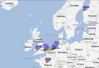
My new 500kHz transverter has "done the business" with reception this evening of my WSPR signal (for the third autumn running) by OH1LSQ at a distance of 1736km. What I find incredible is that this is with low milliwatts ERP from an antenna that is tiny: the outer of the 6m vertical coax (the feed to my 10m halo) tuned against a ground formed by my central heating system copper and brought to resonance with a tapped coil on a ferrite rod sitting on the shack desktop.
500kHz WSPR reports map
The new 472kHz band is clearly going to be great fun for all, even without anything special in the way of antennas. However, my experience with small antennas on 136kHz is a different matter: on that band it is MUCH harder to get reports from any distance with QRP.

For details of my 472/500kHz transverter see https://sites.google.com/site/g3xbmqrp/Home/472khz-transverter

20 Sept 2012

472/500kHz transverter FINISHED

Today I completed the rev E version of my 10W transverter. In the end I reverted to a double balanced mixer and this immediately solved my issues with mixer stability that I had with the transistor mixer design. Air testing this evening, I am getting plenty of reports but a slight drive is noticable in the reports, probably as I am using a small plastic box and the PA heatsink warming is causing the 3.2MHz crystal to move about 1Hz during the WSPR TX cycle. It really needs a bit bigger metal box, but it will do.


The lastest transverter schematic (there may be value errors)
WSPR reports 20.9.12 with the above transverter and 6m long antenna
The desktop 472/500kHz station, ATU (don't laugh!) and antenna current meter

18 Sept 2012

472kHz transverter - real progress

Since reverting to a passive double balanced mixer based design, the circuit is now behaving properly with no signs of oscillation and a good clean signal from the PA. Although I have used an SBL1 mixer, it will work with any similar mixer package. Tomorrow I may try the design with an NE602 as this would allow the separate oscillator to be removed. With an NE602 it should be possible to do the complete TX-RX transverter with 1 IC, 2 transistors and 1 FET.  Now THAT would be neat.

16 Sept 2012

472kHz transverter "progress"?

This afternoon, after a break of a few weeks, I went back to my 10W 472kHz transverter design. The intention was to simply build a second sample to prove repeatability. As is often the case, things didn't quite work out that way: instead I discovered an MF oscillation when drive was removed in some situations. Despite trying all the usual tricks so far, I've not managed to fix it yet. It is not the PA: driving it and the squarer stage directly with a 472kHz signal all is well. It looks like a problem around the oscillator and mixer but so far I have not managed to tame it. Also, and this is probably the same issue, on RX there is a wideband noise resulting in desensitisation. For this evening I have stopped work and will take a fresh look tomorrow. Maybe the double balanced mixer in my original 2010 circuit was not such a bad idea after all.

This is a classic situation when a spectrum analyser would really help as I could see in an instant where the trouble was by poking around with an RF probe and observing the spectrum on the analyser.

5 Sept 2012

On with the projects.....

Back home now, so it is on with the autumn projects list.

Several people have been contacting me about the latest 472/500kHz 10W transverter. Someone in OK-land is designing a PCB and I hear a "dead bug" version has been successfully built in the USA - not sure whether an exact copy or "based on" - but it has already been used on MF WSPR with a report from over 2000km up the USA east coast. So, I will continue with refining this design first and then get on with the "WIPSY" 28MHz simple WSPR transceiver next.

The non line-of-sight optical beaconing tests will resume a little later when the evenings start to draw in. I want to set up a more powerful, semi-fixed 481THz optical beacon so that I can do a series of DX tests under various degrees of cloud cover. Tests last winter suggest much further will be possible than the 9km NLOS ranges achieved with clear air scatter when signals were audible by ear. By using much lower sub-carrier frequencies the optical detector sensitivity will be very much greater allowing even weaker signals to be detected on QRSS3 and QRSS30.


22 Aug 2012

The second 472kHz transverter (with MeSquares)

Partially built 472kHz transverter using MeSquare islands
This afternoon I started the build of my second 472kHz 10W transverter to confirm repeatability of the design. This time I'm using MeSquares from www.qrpme.com as islands to aid construction. The build is about 75% complete so I thought I'd take a photo to show the technique before the board gets too crowded. With some care the results can be almost as neat as a PCB.

27 Jul 2012

Updated MF transverter schematic

The current Rev D version of the 10W MF (472/500kHz) transverter is shown below. There are a few changes around the PA and output filter.
Revised 10W transverter schematic (27.7.12)

25 Jul 2012

New MF transverter ready for testing

472/500kHz transverter built more presentably
Being satisfied with the latest 10W version of my 472/500kHz transverter breadboard, I have now rebuilt it more tidily so it will fit in a small plastic or diecast box. This uses my normal "dead bug" construction using a piece of copper laminate as ground plane with small PCB pad islands to join some components. It will be tested tomorrow, but I am not expecting any issues.

UPDATE 26.7.12
Tested the transverter above on-air this evening and getting reports from several stations on WSPR.
WSPR reports so far this evening on 500kHz

21 Jul 2012

Results with the new 500kHz transverter

WSPR reports received this evening (40mW ERP)
A decent evening testing the new 472/500kHz transverter with WSPR reports from 6 different stations (best DX 440km) and copying 3 different stations on OPERA Op4 mode. There is still a slight PA instability that needs to be fixed (probably decoupling changes), so there is a bit more optimisation to do.

472/500kHz transceive transverter

Rev C Transverter (one correction: o/p LPF cap 6n8, not 100n)

Armed with the sensitivity data in the last post I have now modified my MF transverter to add the receive parts, without a preamp. I used the same scheme adopted in my old transverter to automatically switch through the 500kHz (or 472kHz) signal on receive directly to the FT817. Only 4 additional parts were needed to make it into a TX/RX transverter.  As proof that the RX part is working I have just copied PA0WMR with a huge signal on OPERA Op4 with the signal passing through the transverter.

20 Jul 2012

472/500kHz TX transverter - first schematic

10W 472/500kHz TX Transverter (CW, WSPR, OPERA, QRSS)
OK, here is the first schematic (subject to corrections, changes and improvements) of my simple TX transverter for 472 or 500kHz. This one needs no expensive parts and went together painlessly. The PA filter parts used the GW3UEP approach of winding thickish copper wire (1mm in my case) onto 22mm white PVC drain pipe pieces. The mixer, LO and squarer stage all use ubiquitous 2N3904 transistors (my favorite!) and the PA a cheap IRF510 FET that produces 10W RF without even getting warm.

Next stage is to add the RX preamp and filter and sort out RX-TX switching. I also want to try to go for a higher PA output power which will require changes to the output network.

15 Jul 2012

500kHz tranverter (Mk 2) breadboarding

This weekend I've made considerable progress with the new transverter for 472 and 500kHz and fully breadboarded a 10W TX transverter.

My objectives are to make the design simpler than the original 2010 design  (no expensive SBL1 double balanced mixer!), produce more power and improve the RX performance. Also I want to reduce the need for special parts such as toroids.

The design evolving is, like all my designs, a mixture of my own ideas and the best from other people. When the design is ready I will put it here and on my main website. I've moved away from 28MHz IF (too high, too much start-up drift) and instead gone to 3.7MHz using a 3.2MHz crystal available from GQRP inexpensively. The TX mixer (none is needed on RX as it is uses the FT817 in split mode receiving directly on MF) is a simple bipolar stage followed by a low pass filter. For the PA I have largely copied GW3UEP's excellent designs for a 25 (and later 100W) amplifier. Initially I am using an IRF510 from 13.8V and getting around 10W RF out. The next stage is to look at the RX front end. I want a little gain ahead of the FT817 but with good large signal handling and decent filtering. The FT817 works OK at 500kHz but is a little deaf.

So, a satisfying few hours building.

20 Jun 2012

Back home again and the 472kHz transverter

Icefield Parkway, Alberta
After nearly a couple of astounding weeks in British Columbia and Alberta, Canada my wife and I are now back home. The scenery and wildlife were just amazing, especially the bears like the one below seen just a few metres away from us.  Although I only managed about an hour of shallow sleep on the plane back from Calgary last night I decided it was better to fight the jet-lag and get on with some chores rather than crash out and wake at 2am tomorrow.

One of the 8 black bears we encountered - this one VERY closely
Once the lawns have been trimmed and the hedge cut, I've decided to crack on with the design of a new transverter for 472-479kHz as the next project. Already there is activity from Germany and there are a number of NDB beacons to allow the receiver part to be checked. Jan 1st 2013 (the likely date of release in the UK) will arrive far too soon.

I am trying to decide on the choice of IF as I want to use an unmodified FT817. 28MHz will allow 472-479kHz to appear "in-band", but at 28MHz the start-up drift as the LO settles will still be some tens of Hertz. This hasn't proved problematic with WSPR, so guess this is my choice. At least the dial will directly read the "right" frequency e.g. 28.477kHz will correspond to 477kHz.

In view of the picture above, I am not sure what power the transverter will use bear-foot (sorry, weak joke).


20 Jan 2012

137kHz transverter bites the dust

Having re-erected my 80m loop antenna I was about to reload OPERA and give it a try now it appears more stable. I ran up the transverter on WSPR to check all was well only to have the power supply suddenly take around 20A and shut itself down.  I think the MOSFET PA died on me. All being well I will get this fixed next week when my grandson goes back home again and have another try.

17 Nov 2011

137kHz transverter picture

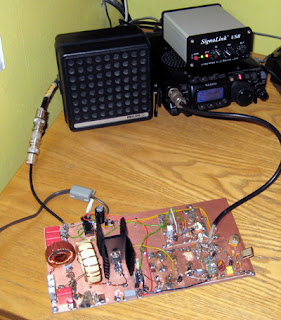
137kHz transverter with FT817 and SignaLink USB in the background
Thought people might like to see the current version of the 137kHz transverter used for WSPR transceive. The heatsinks are total overkill as they barely get warm when producing over 20W RF into the loop antenna. I am regularly getting reports from a couple of stations 250km away. M0BMU (69km) and G0WCB (101km) are reporting the WSPR signals almost all the time. It works but needs boxing, when I get time.