My apologies for lack of recent content, but we've been away from the home QTH whilst our kitchen is being refitted. The local builder, a good and reliable person, advised us to go away and avoid the chaos, so we have been exploring Kent and East Sussex from our son's home near Canterbury. No ham gear with me, just the iPod Touch 4g.
Update Aug11th: we have now returned home (PW awaiting me) to find the kitchen almost finished - 2 more days work - and looking good. Problem is access to my "lab" is impossible because of boxes and builders tools. With luck all should be clear by Wednesday when ham radio building can resume.
10 Aug 2012
CW from Mars
The latest NASA rover "Curiosity" apparently imprints JPL in CW on the Martian surface as a result of its tyre pattern. See http://www.tyrepress.com/News/OFFBEAT/25967.html . If I recall correctly my callsign is on a microchip on "Curiosity" (see post last autumn).
2 Aug 2012
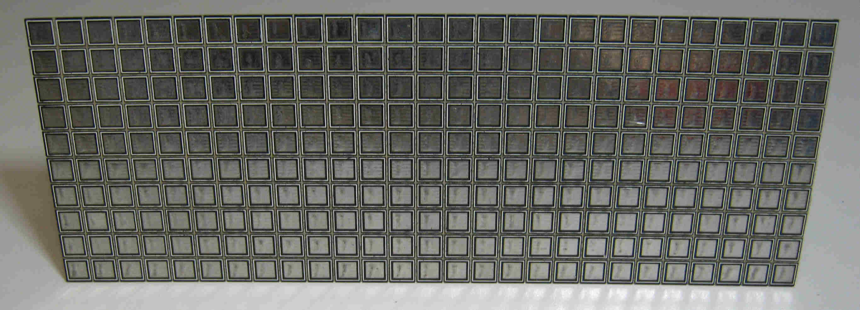
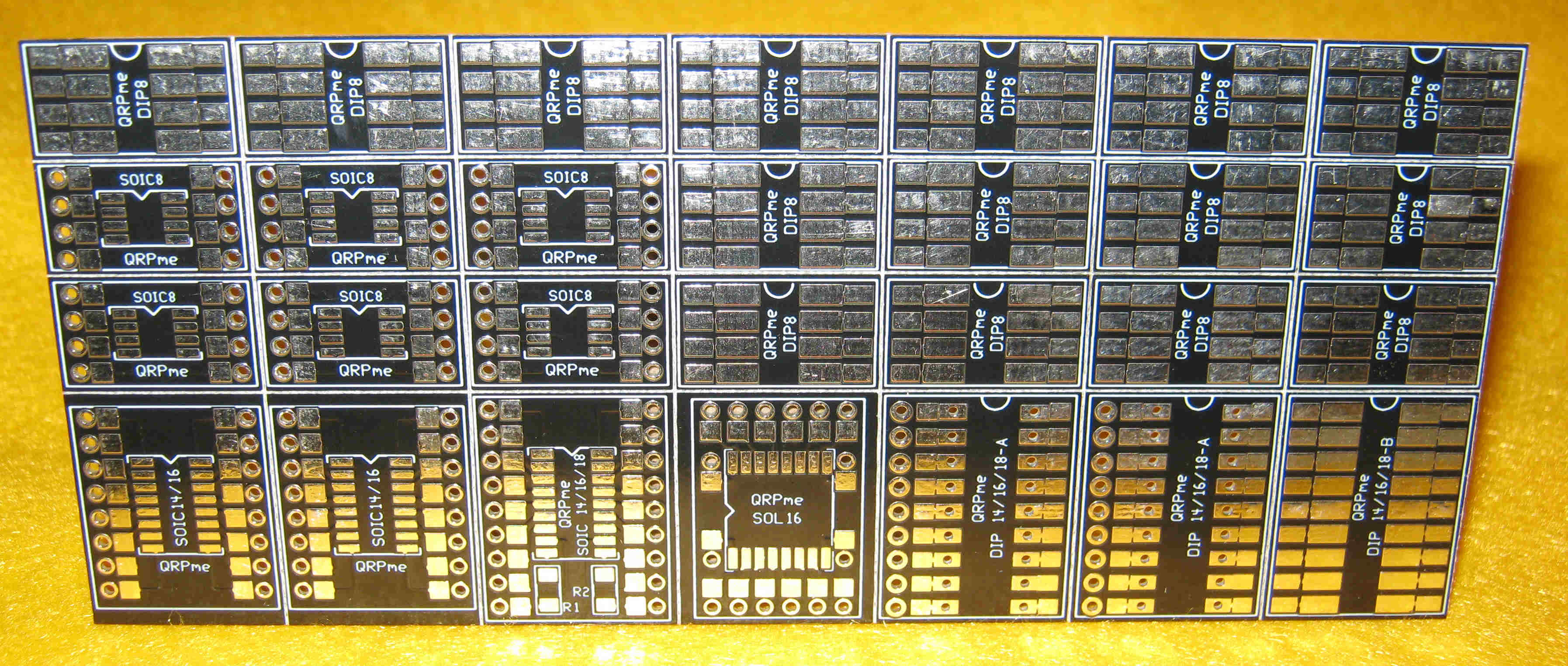
MePADS and MeSQUARES
 |
| MeSQUARES |
 |
| MePADs |
31 Jul 2012
Finally RIP Heathkit
It was a long time finally dying after the last Heathkit amateur radio product was made by this once fine company, but I read today on the Southgate Amateur Radio News page that what was left of the company has now filed for bankruptcy. Latterly it had been involved in educational systems but funding was drying up.
Founded in 1926, Heathkit was famous for its kits in the 1950s, 60s and 70s. They were the Elecraft of their day with sound designs and clear step-by-step building instructions. My first introduction into electronics and radio was with a kit for Christmas 1961. I never looked back thanks to that wonderful product.
I hope VE6CN wont mind me linking to his picture showing his fine line-up of Heathkit products. For a lot more pictures of Heathkit amateur radio products see http://www.ultrawebb.com/OHP/gallery.htm .
 |
| VE6CN's fine line-up of Heathkit products |
I hope VE6CN wont mind me linking to his picture showing his fine line-up of Heathkit products. For a lot more pictures of Heathkit amateur radio products see http://www.ultrawebb.com/OHP/gallery.htm .
Sub-harmonic mixer based 10m WSPR transceiver
 One neat idea is to use a 14.060MHz crystal (cheap from GQRP) pulled up to 14.0623MHz (it is possible) and use this to drive a Polyakov sub-harmonic mixer, which needs half frequency drive, in a simple direct conversion receiver feeding a PC sound card via an isolating transformer. The same oscillator, doubled would be fed into a single balanced DSB modulator and a small QRP PA stage. The resulting WSPR signal would appear as a DSB signal , not SSB, so half the power would be wasted but who cares with milliwatts?
The resulting full WSPR transceiver would be extremely small and simple, need no VFO or VXO and could be left running almost continuously when the PC is switched on. This would be ideal with a small netbook PC.
The idea is not new: see for example http://www.qsl.net/d/dl1gsj/html/qrssrx30.html .
Sounds like this is my next project......
Elecraft KX3 user satisfaction poll
A few weeks ago I ran a poll on the Elecraft KX3 Yahoo group asking owners how satisfied they were with the KX3 QRP radio released earlier this year. I don't own one of these radios, but do covet one. Poll results can be interpreted in a number of ways, but I think this is a fair summary:
So, will I buy one? Not sure. What is certain is that if I ordered one today I'd be unlikely to see one in my hands much before Christmas such is the backlog and demand.
- 65% of respondents found the KX3 exceeded or far exceeded their expectations.
- 24% of respondents found it met their expectations
- 9% were to some extent disappointed with the product
So, will I buy one? Not sure. What is certain is that if I ordered one today I'd be unlikely to see one in my hands much before Christmas such is the backlog and demand.
27 Jul 2012
Updated MF transverter schematic
The current Rev D version of the 10W MF (472/500kHz) transverter is shown below. There are a few changes around the PA and output filter.
 |
| Revised 10W transverter schematic (27.7.12) |
The Lesser Chirpy 10m CW transceiver
SPRAT 151 had my article on Chirpy, an ultra-simple, very basic crystal controlled CW transceiver for 28MHz. This does work and has even managed a few decent QSOs but, boy, does it chirp! So, today I followed up on an idea I had to reduce the chirp by FSKing the oscillator when on TX. The schematic is attached.
The basic idea is to switch to TX by closing S1 (increases the oscillator output to around 150mW) then key a capacitor in series with the crystal. As the oscillator is on at full power with the key off or on (FSK shift) the chirp goes. There are a couple of disadvantages (a) the rig is no longer full break-in, and (b) when the key is up there is the "opposite" morse about 1kHz up the band, which is wasteful of power and may confuse. Still, this is a "for fun" rig and, with virtually no chirp, a much better radio. As before, a small low pass filter on the output is advisable unless your ATU provides this.
I also adjusted the turns on the main collector inductor finding that a tap 3t from the cold end worked better. You will almost certainly have to experiment with the values of capacitance around the crystal and key to get the right amount of TX-RX offset.
UPDATE 29.7.12: corrected the circuit diagram (crystal going to wrong place!)
472/500kHz video
26 Jul 2012
472/500kHz antenna improvements needed
For the last month whilst testing my 472/500kHz transverter I've been using a highly compromised antenna. Essentially it is a very short Marconi tuned against my central heating system ground. The first 6-7m is a coax cable running next to pipes in the loft horizontally. Eventually the coax runs outside and up 5-6m to my 6m/10m halos. The coax inner and outer are strapped together when used on 500kHz. In the last week we have had a new central heating boiler fitted, this time in the loft, so there are even more copper pipes and wires running close to the coax. Reports appear to be a few dB worse on 500kHz as a result.
The time has now come to design a "no compromise" 500kHz Marconi! Looking at the geometry of my garden I should be able to erect a 5-6m vertical away from the house with some 10m of horizontal top loading. I can add some inductance near the top of the vertical section and tune it all against a reasonably decent ground (4 x 1m long earth spikes, a couple of radials and the central heating copper). Not sure how soon I can work on this but I would hope the ERP increase could be up to 6dB. At least with WSPR (and OPERA) one can do a series of tests over several days with each antenna and compare results. It will be easy to measure antenna current which gives a good indication of ERP when the antenna effective height is calculable.
The time has now come to design a "no compromise" 500kHz Marconi! Looking at the geometry of my garden I should be able to erect a 5-6m vertical away from the house with some 10m of horizontal top loading. I can add some inductance near the top of the vertical section and tune it all against a reasonably decent ground (4 x 1m long earth spikes, a couple of radials and the central heating copper). Not sure how soon I can work on this but I would hope the ERP increase could be up to 6dB. At least with WSPR (and OPERA) one can do a series of tests over several days with each antenna and compare results. It will be easy to measure antenna current which gives a good indication of ERP when the antenna effective height is calculable.
Labels:
472-479khz,
500kHz,
antenna,
marconi
Subscribe to:
Comments (Atom)


