I have added a page on my main website showing the VLF earth-mode beacon transmitter currently being used. In the next few days I'll add the article that appeared in RadCom in 2011 which shows the schematic as well as some more details of the recent tests.
At the moment, my earth-mode tests are on hold. I am finding more and more of my time is being taken up preparing for our house move. At some point in the next few weeks it will be time to take down the V2000 VHF/UHF vertical and the other antennas. It is a long time since I've had no antennas up at all! With luck I'll soon have them back in place at the new QTH and I can start DXCC chasing (gently!) from scratch again. I wonder how long it will take to work my first 100 DXCC countries with modest antennas at the new QTH?
The new home has a totally different shape garden and I shall be intrigued to find out how well (or not) an earth-electrode antenna works on VLF, LF and MF. A 20m baseline spacing between electrodes should be possible by placing the remote electrode at the far corner of the garden with the feed wire diagonally across the garden.
27 Jun 2013
23 Jun 2013
What happened to my PC memory?
My 7 year old Dell laptop with 30GB hard drive decided to tell me that I had no memory left today. I did the usual tricks: ran CCleaner, emptied the recycle bin got rid of lots of temporary files etc but still seemed to have freed up only a little. Then I searched the C drive for large files not in My Documents and sub-folders. To my amazement I found WSPRX and other similar programs had been storing WAV files of every time I'd used the software! In total over 5GB of disk space. Having cleared these - no doubt there is an option to stop saving these - and moving little used files off the PC, I now have over 14GB of space. After a defrag and a full virus scan it is ticking along nicely. MS Essentials does a good job of keeping the rubbish out and CCleaner is excellent for house keeping.
SAQ (17.2kHz VLF) transmission June 30th 2013
It is always fun to listen on 17.2kHz for the special test transmissions from the historic Grimeton alternator transmitter in Sweden. Lars Kalland writes:
"We will remind you of the Grimeton Radio/SAQ transmissions on 17.2 kHz, CW, with the Alexanderson alternator on Sunday, June 30, 2013, “Alexanderson Day", at 09:00 UTC and 11:00 UTC. We will start tuning up some 30 minutes before message. "
They welcome reception reports for these SAQ transmissions either via info@alexander.n.se , via the Swedish QSL bureau or direct to:
Alexander-Grimeton Veteranradios Vaenner,
Radiostationen
Grimeton 72
SE-432 98 GRIMETON,
SWEDEN
(NB: new address)
The QSL card from SAQ is something quite special. I was lucky enough to receive one a few years ago. Also see their website at www.alexander.n.se .
A suitable downloadable software receiver (needs a wire connected to the audio input of a PC sound card - add back-to-back diodes to prevent damage) is available at https://sites.google.com/site/sm6lkm/saqrx/.
22 Jun 2013
Eagle comic and a mystery book

One of the regular articles in Eagle was a strip-cartoon called "Professor Brittain Explains" in which a professor shows 2 youngsters how things work like a coal mine, parliament, weather forecasting etc.
Does anyone remember a hardback book along the same lines as the "Professor Brittain Explains" format that was available in the mid/late 1950s in the UK?
Unless my memory is playing tricks, I had this book as a child and enjoyed looking at it for hours and hours yet I cannot remember the title or the publisher, so searching for it on the internet has proved impossible.
If anyone can remember the title of this book, the date it was published or the name of its publisher I would be immensely grateful and I'd pay generously for a copy. I have been searching for it now for close on 40 years without success. My hope is that someone out there still has a copy and this jogs their memory. I've asked before and not been successful. The book is entirely in strip cartoon format with the professor explaining to the children about a particular topic on each page. It must have around 100-150 pages.
Trigger any memories? Hidden in the bookcase?
20 Jun 2013
Finningley optical transceiver working fine
Although I posted this on the Nanowaves Yahoo group , I forgot to update folks reading this blog on the progress with this optical transceiver kit designed by Bernie G4HJW.
Well, at the weekend I finished building the unit and started testing it. The TX part worked first time, but the RX did not. Time to find out why!
Using logic and common sense, I carefully went through the various stages (8V regulator, later audio stages etc) and tracked the fault down to an intermittent preset SMA pot that sets the FET bias. The FET stage is the very high impedance stage that follows the PIN photodiode.
The error was entirely my fault and easily fixed by removing the part and redoing the surface mount joints. Now the full transceiver is working well (but yet to be put into 100mm optics) and the RX sensitivity is close to that with my K3PGP design RX. In the coming weeks I hope to get a transition piece to connect the transceiver "tube" to a 110mm drainpipe that houses the 100mm lens. I'll then assemble this onto a stable tripod with sighting scope and I'll be ready to look for QSOs.
One thing that puzzled me was how having the detector diode and TX LED slightly off-centre would work. In my mind I thought that the light would not be properly focused onto the devices, so losing sensitivity. Then someone pointed out that by slightly aiming "off beam" by around 1 degree the light would fall exactly onto the position on the transceiver where the LED or PIN diode are mounted.
Well, at the weekend I finished building the unit and started testing it. The TX part worked first time, but the RX did not. Time to find out why!
Using logic and common sense, I carefully went through the various stages (8V regulator, later audio stages etc) and tracked the fault down to an intermittent preset SMA pot that sets the FET bias. The FET stage is the very high impedance stage that follows the PIN photodiode.
The error was entirely my fault and easily fixed by removing the part and redoing the surface mount joints. Now the full transceiver is working well (but yet to be put into 100mm optics) and the RX sensitivity is close to that with my K3PGP design RX. In the coming weeks I hope to get a transition piece to connect the transceiver "tube" to a 110mm drainpipe that houses the 100mm lens. I'll then assemble this onto a stable tripod with sighting scope and I'll be ready to look for QSOs.
 |
| http://www.earf.co.uk/optoposition.JPG |
How much am I RADIATING at VLF?
As a matter of interest, this afternoon I worked out how much power I am actually radiating when carrying out my earth-mode tests. The main transmission mode is conduction through the soil/rocks and buried utilities, but an earth-electrode antenna will produce some very very small amount of radiation too.
The first thing is the effective area of the "loop in the ground" and based on a guestimate of 40 ohm metre soil resisitivity (could be somewhere between 10-100 ohm metres) my calculations give me an effective loop area of 600m sq at 8.97kHz - i.e. the signal current flows quite deeply into the ground.
The second figure is the current flowing in the loop (I) which I measure as 0.2A using a current transformer to sense the current.
Rrad = (31171 x Ae^2)/lambda^4 = 0.94 *10^-8
Lambda = 33km
Ae = 600 sq m
I = 0.2 amps
Rrad = 0.94 * 10^-8 ohms
ERP = I^2 x Rrad
So, plugging in the numbers:
ERP = 0.2 x 0.2 x 0.94 x 10^-8
ERP = 37nW
There may well be errors in my sums and in the assumptions made, but clearly 37nW is a tiny amount of radiated power and (almost) negligible. To get to a level where the radiated signal is detectable over 100km away, I would need to radiate around 4-8uW, i.e. several orders of magnitude more. Radiation resistance is proportional to the loop area squared so increasing the baseline by a factor of 10 increases the radiation resistance by 100 times. This could be helped with a much longer baseline (200m long rather than 20m) and increasing the power into the earth-electrode loop to 500W and elevating the loop part that feeds the far earth electrode with current. Such changes could result in a radiated power level of around 4-8uW based on the assumptions about soil/rock resistivity and skin depth. A 200m long piece of wire (e.g. along a field edge) and 500W of audio power are not that hard to envisage and a LOT easier than winding a huge loading coil and raising a kite supported antenna several hundreds of metres high.
Progress with the new shack

VLF earth-mode "propagation" variations
In the last few weeks I have been doing QRSS3 (slow CW) tests at approximately 1kHz, 4.48kHz, 8.97kHz and 18kHz transmitting 5W into 20m spaced earth electrodes (1 electrode at the bottom of the garden and the other connection to house copper pipes) and checking signal strengths at 1.6, 3.6 and 6km away from the home QTH using my portable loop antenna, preamp and a small netbook PC running Spectran software. Propagation is by utilities assisted earth-mode i.e. the main means of signal propagation is (I believe) conduction through buried pipes and cables with the induction field at the RX point being picked up with the loop. I have also used an E-field probe to detect the E field signal at some distance.
The recent tests were to see how signal levels varied with frequency, but I am finding VERY large differences in signal level day-to-day. The 8.97kHz signal was around 10dB S/N today at 1.6km whereas it was around 20dB S/N a week or so ago. I was unable to copy a signal at 1kHz and 8.97kHz at 6km at all when I tried a few days ago yet the 8.97kHz signal was quite decent a few weeks ago at the very same spot.
There will be some dBs variation depending on the exact positioning of the RX loop on the ground but the variations seem suggest something else. Today there were a lot of static crashes and I don't know if this upsets Spectran's DSP processing? The other variation could be soil conductivity: today was wet (raining) whereas the best results seem to be with dry settled conditions when the soil has dried out a bit.
Conclusions so far? Signal strengths between 1-17kHz at 6km range don't vary that much over the frequency range, but signal levels can be up to 20dB different day-to-day as a result of other (as yet not understood) variables in the system or path.
The recent tests were to see how signal levels varied with frequency, but I am finding VERY large differences in signal level day-to-day. The 8.97kHz signal was around 10dB S/N today at 1.6km whereas it was around 20dB S/N a week or so ago. I was unable to copy a signal at 1kHz and 8.97kHz at 6km at all when I tried a few days ago yet the 8.97kHz signal was quite decent a few weeks ago at the very same spot.
 |
| Weaker 8.97kHz received signal at 1.6km today |
 |
| Weak 4.485kHz received signal at 1.6km today |
Conclusions so far? Signal strengths between 1-17kHz at 6km range don't vary that much over the frequency range, but signal levels can be up to 20dB different day-to-day as a result of other (as yet not understood) variables in the system or path.
18 Jun 2013
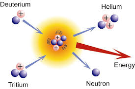
The ITER project - first realistic steps to clean nuclear fusion power?
ITER, a nuclear fusion project funded by many nations, is assembling the biggest nuclear fusion test reactor ever, in France. Due to "go nuclear" in the 2020s, this unit should produce 500MW for every 50MW put in as a result of the fusion process. Unlike nuclear fission, nuclear fusion has the potential for almost limitless nuclear energy without the radioactive waste risks associated with nuclear fission. Even with a successful project, commercial nuclear fusion reactors are unlikely until the second half of the 21st century.
 A LOT is at stake here: nuclear fusion, if the technical issues are overcome, could be a saviour for the human race at a time when energy resources are likely to be in short supply at a time when demand will be at an all-time high.
Man's ingenuity is such that even the technical challenges of fusion will be overcome when the imperative is great enough. I have faith in the ability of scientists and engineers (and even in politicians) to come up with the solutions in time to help produce a better world for my children and grandchildren. It's just a pity I shall not be around to see it.
Man's ingenuity is such that even the technical challenges of fusion will be overcome when the imperative is great enough. I have faith in the ability of scientists and engineers (and even in politicians) to come up with the solutions in time to help produce a better world for my children and grandchildren. It's just a pity I shall not be around to see it.
6m WSPR
For the last 36 hours I have been using WSPR on 6m to check for openings when busy with other things. I am surprised how often CN8LI (2171km) and I exchange spots even though I have only been running 500mW into the vertical V2000 antenna. I assume this is Es, but the path seems too consistently open for Es somehow.
I am disappointed more stations in the USA and Canada are not active on 6m WSPR: with a good number of stations both sides of "the pond" active, it would be an excellent way to spot those fleeting multi-hop Es openings at any time of the day or night.
I am disappointed more stations in the USA and Canada are not active on 6m WSPR: with a good number of stations both sides of "the pond" active, it would be an excellent way to spot those fleeting multi-hop Es openings at any time of the day or night.
Subscribe to:
Posts (Atom)


