20 Jun 2013

VLF earth-mode "propagation" variations

In the last few weeks I have been doing QRSS3 (slow CW) tests at approximately 1kHz, 4.48kHz, 8.97kHz and 18kHz transmitting 5W into 20m spaced earth electrodes (1 electrode at the bottom of the garden and the other connection to house copper pipes) and checking signal strengths at 1.6, 3.6 and 6km away from the home QTH using my portable loop antenna, preamp and a small netbook PC running Spectran software. Propagation is by utilities assisted earth-mode i.e. the main means of signal propagation is (I believe) conduction through buried pipes and cables with the induction field at the RX point being picked up with the loop. I have also used an E-field probe to detect the E field signal at some distance.

The recent tests were to see how signal levels varied with frequency, but I am finding VERY large differences in signal level day-to-day. The 8.97kHz signal was around 10dB S/N today at 1.6km whereas it was around 20dB S/N a week or so ago. I was unable to copy a signal at 1kHz and 8.97kHz at 6km at all when I tried a few days ago yet the 8.97kHz signal was quite decent a few weeks ago at the very same spot.
Weaker 8.97kHz received signal at 1.6km today
Weak 4.485kHz received signal at 1.6km today
There will be some dBs variation depending on the exact positioning of the RX loop on the ground but the variations seem suggest something else. Today there were a lot of static crashes and I don't know if this upsets Spectran's DSP processing? The other variation could be soil conductivity: today was wet (raining) whereas the best results seem to be with dry settled conditions when the soil has dried out a bit.

Conclusions so far? Signal strengths between 1-17kHz at 6km range don't vary that much over the frequency range, but signal levels can be up to 20dB different day-to-day as a result of other (as yet not understood) variables in the system or path.

18 Jun 2013

The ITER project - first realistic steps to clean nuclear fusion power?

ITER, a nuclear fusion project funded by many nations, is assembling the biggest nuclear fusion test reactor ever, in France. Due to "go nuclear" in the 2020s, this unit should produce 500MW for every 50MW put in as a result of the fusion process. Unlike nuclear fission, nuclear fusion has the potential for almost limitless nuclear energy without the radioactive waste risks associated with nuclear fission. Even with a successful project, commercial nuclear fusion reactors are unlikely until the second half of the 21st century.

A LOT is at stake here: nuclear fusion, if the technical issues are overcome, could be a saviour for the human race at a time when energy resources are likely to be in short supply at a time when demand will be at an all-time high.

Man's ingenuity is such that even the technical challenges of fusion will be overcome when the imperative is great enough. I have faith in the ability of scientists and engineers (and even in politicians) to come up with the solutions in time to help produce a better world for my children and grandchildren.  It's just a pity I shall not be around to see it.

6m WSPR

For the last 36 hours I have been using WSPR on 6m to check for openings when busy with other things. I am surprised how often CN8LI (2171km) and I exchange spots even though I have only been running 500mW into the vertical V2000 antenna. I assume this is Es, but the path seems too consistently open for Es somehow.

I am disappointed more stations in the USA and Canada are not active on 6m WSPR: with a good number of stations both sides of "the pond" active, it would be an excellent way to spot those fleeting multi-hop Es openings at any time of the day or night.

Low cost, high performance 10GHz receiver

Recently Ian G3KKD has been telling me about some remarkable results on 10GHz using an Octagon satellite LNB that is available for around £12-15 via eBay. This has a crystal controlled PLL and has good frequency accuracy, stability and phase noise. I believe the LNB outputs a signal around 600MHz which is then down converted to a suitable IF.

Using this set-up Ian can copy the 10GHz beacon GB3CAM at around 30km with just the LNB handheld in his front or back garden which is badly screened by tall trees! Using a small Sky dish, the signal is S9+60dB from a point just along the road.

Of course, with a small surplus satellite dish, a low cost TV USB dongle used as an SSB/CW RX at the LNB output frequency, this would make an excellent SDR for 10GHz with VERY low noise figure. The LNB quotes the NF as 0.1dB, which is remarkable.

With a small 10GHz FM or CW TX into a separate dish, a complete low cost 10GHz station is possible, probably for less than £50. I am sorely tempted to try this.

I have just seen Andy G4JNT's note about this http://www.g4jnt.com/PLL_LNB_Tests.pdf .

Earth-mode at 1kHz and 18kHz today

As a follow-up to my recent tests at 8.97kHz, today I repeated the QRSS3 earth-mode (through the ground) tests with my latest receiving equipment but this time at around 18kHz and 1.1kHz.  TXing at 18kHz is legal as there is no appreciable radiation. As before, the TX was 5W into earth electrodes 20m apart back at home. I wanted to see how signal levels varied compared with 8.97kHz at my 3 usual test sites out to 6km distance from home.

Results were interesting: although signals were copied at 1.6km and 3.6km on both test frequencies, nothing at all was copied at 6km, where very good signals were copied on 8.97kHz a few weeks ago. Ground conductivity and weather conditions were identical on both test days: dry for the last several days, so conductivity likely to be lower than when the fen soil is saturated.

I have no real idea why 8.97kHz should appear to be a "sweet spot" in frequency. It is possible that other frequencies lower than 8.97kHz and higher than 1.1kHz may be even better. In all cases the RX loop was resonated and positioned on the ground varied for best signal.
1.12kHz earth-mode signal at 1.6km

17.952kHz earth-mode signal at 1.6km
1.12kHz earth-mode signal at 3.6km
17.952kHz earth-mode signal at 3.6km (note MSK signals close by)

14 Jun 2013

Low costs SSB "Pixie" from Argentina

Pedro LU7HZ has sent me an update on work in Argentina on a low cost approach to an HF QRP SSB transceiver using very few parts. Basically they are using simple electronics coupled with an SDR approach to the modulation and demodulation process.  My own approach would be the fully low tech approach (for a CW/DSB rig) but Pedro's approach is innovative and worth watching. I hope he produces kits or, at the least, documentation to allow others to duplicate the idea as it comes to fruition.
Roger,

This is a project we've been working together with Willoh (LW3DYL) which fits partially into your quest for an extremely low cost and easy to build rig ("UKP 20 decent HF...") although not using the low tech approach but the other way around.

The design is still being debugged and more simplifications will be attempted (such as a more simpler TR/RX switch and eliminate the 7474 based quadrature filter replacing it by an RC approach. The net result should be a one IC and 4 transistors design plus PA final.

The design uses an USB power source (out of an inexpensive cell phone switching power supply or straight out of the USB port at the PC) having 0.5W with it; more like 1W with +12V.

Main software platform will be a modified version of KGKSDR. Main use should be CW or SSB although no reason why not to use it with PSK or FreeDV or WSPR.

Should fit on a (small) pocket.


Main limitation so far is available time from the builders to devote to the project.

73 de Pedro LU7HZ
Dr. Pedro E. Colla
Va.Belgrano-Ciudad de Cordoba
Cordoba- Argentina
"La vida no es esperar a que pase la tormenta, es aprender a bailar bajo la lluvia". Anonimo

Finningley optical transceiver progress

In the last couple of days, armed with my wife's close-up reading glasses, a magnifying glass, tweezers and a fine tipped soldering iron, I have been doing the SMA build of G4HJW's "Finningley" optical transceiver kit, designed to be used with 100mm optics (drain pipe and Poundland lenses!).
The G4HJW designed optical transceiver
Bernie's instructions were first class with all the SMA parts for the receiver and the transmitter being organised sequentially with a clear layout diagram showing where each part has to be placed. It seems to have gone together very well with no snags, although I have still to add a few discrete parts including the LED and the PIN photodiode before testing can start. All being well, I should be able to start testing on Sunday as I am tied up with our church fete tomorrow.

11 Jun 2013

Efficient electrically short antennas

Way back in my early professional life I was responsible for the design and implementation of a tiny 70cm antenna that had to fit inside the Pye PF8 UHF handportable transceiver. The mechanical design team had left virtually no space for the plate antenna we had intended, so yours truly had to come up with a solution that both fitted and worked efficiently. I managed it by changing the plate antenna to a skeleton plate antenna. In the end it worked very well but the tuning was VERY sharp. Reference here should be made the Wheeler and the Chu limit that defines the bandwidth that an efficient electrically short antenna can achieve.

Basically the thing to remember is this: the smaller the antenna is the higher the Q, and the narrower the bandwidth is, for efficient operation. This is why magnetic loops can work well if designed with a very very high unloaded Q and why they have a very narrow bandwidth if working efficiently. It also explains why a short loaded antenna will have a narrower bandwidth if working efficiently.  Dr Underhill has argued that a small magnetic loop actually violates the Chu limit.

There is a good analysis of small antennas at http://www.m0rzf.talktalk.net/RobCentral/E.S.Antenna.html which goes into some of the maths and looks at various electrically small antennas. Some are "snake oil" of course, but some well designed ones do work with the caveat of narrow bandwidth e.g. well designed magnetic loops.

What is the interest in all this for me today? Well, I am still thinking about HF operation at the new QTH and how to meet my goals of a small, low visual impact antenna, that works well. One thing in my favour is I tend to operate on quite small parts of the HF bands e.g. around the WSPR/PSK frequencies or around the QRP frequencies. As long as I am  prepared to stay close to certain frequencies like 28.1246MHz I should be able to design a very small efficient antenna. I already know that a magentic loop antenna works very well indeed and would certainly meet my goals.

10 Jun 2013

Gardening at the new QTH

This evening I've been busy laying some additional turf in the back garden at our new (soon) QTH. About 5sq m of additional lawn was laid with about the same again to be added in the coming weeks. The bundalow is still a bit of a mess with lots of building work ongoing. The new back garden is around 70 feet wide, so an end-fed 1/4 wave for 80m should be possible. Tomorrow evening I hope to plant a new tree in the lawn to provide some screening from the neighbours.  There is a lot of gardening to do to get the place looking as we would like, but it is coming on OK.

I am still deciding what to do about amateur radio and antennas at the new QTH. I dislike large and unsightly antennas, so whatever I do it is likely to be something stealth like. Whatever, it will be a whole new set of challenges to enjoy. At least I shall have a purpose built shack in which I can both operate and build, unlike the present QTH, with a nice view down the length of the back garden.

Incidentally I bought the turf out in the fens - much cheaper than the garden centre. It did involve driving my car into the middle of a large 100 acre field to collect it though (see RHS).

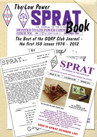
The Low Power SPRATbook.

http://www.rsgbshop.org/acatalog/
Today, my new paper logbook (yes I still use a paper logbook!) and a new book arrived from the RSGB. The book was the Low Power SPRATbook, recently published by the RSGB and edited by Steve Telenius-Lowe 9M6DXX. As I want to de-clutter and possibly clear the book shelves of my old paper SPRAT copies (I still have them on DVD), this book was ideal as it contains a very good selection of the best of SPRAT articles from 1974-2012. If you have not read SPRAT and seen the excellent articles each quarter, then I recommend this book. I challenge you to buy it and not be inspired to build something.

Perhaps I should also mention that my 14 component 80m CW transceiver is one of the articles. But don't let that put you off! The circuit works well and G3XIZ worked GM with his version (despite running only about 18mW) and was copied on Switzerland.