12 Jan 2013

Albrect AE2990 Albrect12/11/10m Multimode handheld

Albrect AE2990 multimode
On G4ILO's blog I noticed a reference to Julian's Albrecht 10m/12m handheld transceiver. A quick search on the net and I see these on sale via eBay for £159. See eBay item number 181059871622. This is also sold as a Magnum 1012.

Although I have used the FT817 handheld lots of times on 15 and 10m and had some excellent contacts with it using a small base loaded whip (a counterpoise definitely helps), I have no experience of the Albrecht unit, which looks like an oversized VHF handie.

Has anyone here used one seriously for handheld DXing? If so, how did it perform?  The interesting thing is this unit can be programmed for 12m, CB or 10m use by changing some solder pad links under the PTT rubber.

I can imagine that this handheld could provide hours of fun during a summer sporadic-E opening, although I would expect results to be disappointing without a counterpoise if using it handheld with ether the supplied whip or a longer whip.

True handheld DXing can be quite a challenge, but great fun.  Actually being able to move  the handheld around to get the best angle can sometimes really help, especially on signals coming in at odd angles. Some time ago I was going to see how many countries I could work on handheld SSB, although I've not seriously tried this lately. I much enjoy handheld DXing when on holiday in Devon from clifftop sites overlooking the sea as in these locations many dB can be gained by chosing a nice location with a slope towards the sea. One of my best contacts was a YV station on SSB (8000km) from my late mother's back garden.

Thoughts turning to 136kHz again

After a few weeks on the new 472-479kHz band, my thoughts are again turning to 136kHz, a band that I experimented with a year or more ago now. This band is MUCH harder work than 472 or 500kHz with around 20-30dB more of everything (!) needed.  By this I mean that for the same power, the "effort" to get a contact or report seems to be about 20-30dB more. This is partly because the short antennas I use have a very low radiation resistance at 136kHz so losses become more significant. Also, noise can be even more of an issue.  Despite all of this, I plan to make a 136kHz version of the transverter I did for 472kHz, but maybe with a bit more RF output (in the 20-30W region). Most of the design is ready done (in my head) so it should only take a few days to do. The plan is to TX using my earth-electrode antenna.

On 136/137kHz there are fewer stations using WSPR, so I will probably use QRSS more. In the past I have made QRSS crystal controlled beacons for this band, but with a transverter and my FT817 I will be able to generate a QRSS signal wherever I want in the band and also be able to have QRSS QSOs.

Does anyone have recommendations for SIMPLE PC program that will allow me to generate QRSS (various speeds) as an audio tone? 

This way I can use my SignaLink USB interface and VOX to send QRSS (or DFCW) using audio tones. Please don't suggest Spectrum Lab unless you can give me a "Noddy guide" on how to use it for QRSS! This is a very good program, but to a simple soul like me it seems like you need a PhD to drive it. In the past I've used it for VLF reception, but it took me weeks to work out how to drive it and every time I go back to it I need to learn it all again. I just want a simple QRSS tone generator.


9 Jan 2013

Earth electrode antenna conclusions (472kHz)

With some further tests today I am now able to arrive at some conclusions from my experiments with an earth electrode antenna at 472kHz. Many people including Jim M0BMU and Rik OR7T have been particularly helpful in analysing the data.
My current 472kHz earth electrode "antenna" - can you see it in the grass?
These are my conclusions:
  1. The earth-electrode antenna at 472kHz (2 earth rods in the soil 15-20m apart fed from the TX output) behaves like an H-field loop transmitting antenna.
  2. It has directivity, with strongest signals in the line of the loop and weakest signals at right angles to it.
  3. It works as an effective RX antenna too.
  4. In my environment the loop looks like about 50-60 ohms resistive, so a good match to my transverter directly without matching.
  5. The structure works because much of the return current flows deep within the soil and rock beneath the earth-electrode antenna. In my case Rik OR7T calculated that the loop area in the ground is effectively 290m sq with a radiation resistance of 0.017 ohm and a loss resistance of 66 ohms.This is a BIG loop!
  6. Performance compared with my 9m high top loaded Marconi antenna averages only around 8dB down, not a bad figure at all, even with the connecting wire on the ground and not elevated at all.
  7. Where no other antenna option is available, the earth-electrode antenna is well worth trying both on 472kHz and on 136kHz both for RX and TX. Although it works well here, your geology may be different and results not the same.
These last few days have been most interesting and, with the help of many people - listeners giving me WSPR reports, advice from others on the Internet forums, suggestions by email - I have been able to do some quite useful science. Thank you one and all.

472kHz RX and TX with Marconi antenna last night

Overnight I was using a 9m high top loaded Marconi antenna on TX and RX WSPR on 472kHz. I have since taken this down so it doesn't interfere withe the latest earth electrode antenna tests.

The performance of this larger,"in the air" antenna was certainly better than the earth electrode antenna, although not by a huge amount (2-14dB). As you can see, I managed my first transatlantic amateur reception on the new band WE6XGR at 5640km amongst the 27 unique RX spots.

472kHz RX spots on Marconi antenna
On TX with the same antenna, results were equally satisfying with 34 unique station reports.
472kHz TX spots on Marconi antenna

472kHz earth electrode antenna: nothing in the air

Today, I took my experiments with an earth electrode TX antenna for 472kHz to new levels by placing the connecting wires on the grass i.e. not elevated at all.  The theory developing is that the earth electrode antenna works by forming a buried loop in the ground with the earth return path being in the soil and rock beneath the structure. If this is so, then even with the wire sitting on the grass there should still be a loop within the ground, so some radiation from it. Results this afternoon prove this is indeed the case. The following are the results with a 20m baseline between the far earth rod and the copper pipe ground at the home end and with the connecting wire just laying on the grass lawn.
472kHz WSPR reports with earth electrode antenna with wire on the lawn

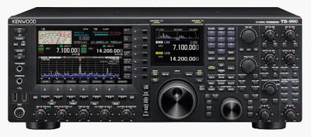
TS990 Press Release

The new TS990 from Kenwood
Readers here will know I'm not a great fan of expensive transceivers: I cannot see the point of spending huge amounts of money on what is, after all, meant to be just a hobby. On top of the expensive transceiver some people go out and spend a fortune on towers, linears, big beams and other expensive accessories. Each to their own: although not my choice it is not for me to say how others spend their hard earned wages.

I see today that the modern cashbook amateur has a new toy to covet: the TS990 from Kenwood. With a price tag likely to be around £9000 it has to be SOME radio. Looking at the spec it does look very impressive. See http://www2.jvckenwood.com/en/news/2013/20130108.html .


8 Jan 2013

Just one slot of WSPR - 15 reports on 472kHz!

Reports in just one 2 minute WSPR time slot with 100mW ERP on 472kHz
With the improved performance from a 9m long Marconi antenna on 472kHz, these were the reports I just got in one single time slot just now. 15 unique stations reported me! It is too easy, even with just 100mW ERP.

How far down is my 472kHz earth electrode antenna on a Marconi?

This evening I have been noting my WSPR S/N reports from stations across the country and nearer Europe using my 9m long Marconi antenna and comparing these with the reports last night when I was using just the 15m baseline earth-electrode "antenna". I crudely plotted the "improvement factor" in dB on a polar plot. Each dot represents a station reporting my signal with the dB improvement over the earth-electrode antenna plotted on a 0-20dB scale out from the centre.

Although in some directions the difference is very little, in other directions the reports are up to 14dB better on the (omni-directional) Marconi.

Stations with dB improvement using the Marconi antenna

M0BMU 10dB
G0KTN 6dB
G3ZJO 5dB
G3WCB 10dB
DL-SWL 2dB
G4HJW 6dB
M1GEO 14dB
G7NKS 6dB
M0LMH 11dB
G0MQW 10dB
G0MQW 10dB

My conclusion is that the earth electrode antenna is behaving somewhat like a loop with directionality along the line of the earth-electrode baseline and a null off the sides. With stations receiving me off the sides there is most improvement with the Marconi, and less difference with stations end-on who were getting a reasonable signal with the earth-electrode antenna.

CONCLUSION: the simple, stealth, earth-electrode antenna is a VERY useful antenna on 472kHz as long as one is prepared to accept a 2-14dB loss compared with a reasonable Marconi.

RFID chips and credit/debit cards

Many credit and debit cards now have embedded RFID chips to allow contactless transactions in cafes. bars etc. Did you realise that your card's RFID chip could be a way of cloning your card's number and expiry date? Neither did I.

Watch this video to see a demonstration of just how easy it can be to someone with the right technology at his disposal.Sounds like a security loop hole that needs fixing fast.

UPDATE: I am reliably informed that this is not an issue in the UK.

A Marconi antenna on 472kHz

So that I can better quantify the performance of my various earth electrode "antennas" I have today erected a 9m long top loaded Marconi vertical for 472kHz. Initial antenna current measurements suggest the ERP is up around 10dB to around 100mW. My plan is to run this overnight again and then tomorrow compare the signal reports against those with my smaller compromise Marconi and my two earth electrode antenna configurations.