At the new QTH, the ham shack will be some way from the wireless router and I will not be able to see if the signal will be usable in the shack for some weeks yet; I have yet to organise the move with the internet service provider. (Reminder to self: contact supplier) Although I could run a network cable through, I'll not do this yet in case the signal proves to be good enough. It means drilling yet more holes in walls and scrabbling around up in the furthermost reaches of the loft, not something I want to do at my age.
Does anyone have any recommendations for WiFi extenders? Maplin and others advertise these but I am concerned about pumping data along mains cables and the resulting QRN likely to be produced, especially in the lower HF spectrum. Does anyone know of one that is electrical quiet, if that is even possible?
In distance terms, the shack is about 20m from where the router is likely to be located, but the microwave signal will have to get through 3 doors (one is metal) and 3 walls. In the current home the router is upstairs and is a decent signal in the lounge downstairs, but through one more door the signal is non-existent. Incidentally I use a recent Netgear super hub supplied by Virgin Media.
27 Jun 2013
WSPR on an Android or iOS tablet?

I asked this before (back in March), but does anyone know if such a WSPR beaconing app is likely soon, if ever? Not being a software guru, I've no idea how difficult this would be, but can see a lot of demand for such an app.
Continuing radiated tests on VLF from Holland
Henny PA3CPM continues to fire up his VLF system on 8.270kHz from time to time. Henny has a very small antenna, just a top loaded 14m long sloper but he manages to get 0.6A antenna current and his signal is now regularly copied several hundred kilometres away by people with suitable antennas, preamps and software. Unlike my own VLF earth-mode transmissions, Henny's signals propagate by radiation. He is a shining example of what can be done with a modest set-up on the so-called "Dreamer's Band". It is no mean feat to radiate a decent signal on VLF with such a small antenna. I have asked Henny for photos of his VLF TX, antenna and loading coil.
Ultimate 2 QRSS beacon TX
 |
| The Ultimate2 QRSS kit |
See http://www.hanssummers.com/ultimate2.html . At just £17.50 this is a great value kit for those interested in weak signal beaconing.
Earth-mode transmitter on my website
I have added a page on my main website showing the VLF earth-mode beacon transmitter currently being used. In the next few days I'll add the article that appeared in RadCom in 2011 which shows the schematic as well as some more details of the recent tests.
At the moment, my earth-mode tests are on hold. I am finding more and more of my time is being taken up preparing for our house move. At some point in the next few weeks it will be time to take down the V2000 VHF/UHF vertical and the other antennas. It is a long time since I've had no antennas up at all! With luck I'll soon have them back in place at the new QTH and I can start DXCC chasing (gently!) from scratch again. I wonder how long it will take to work my first 100 DXCC countries with modest antennas at the new QTH?
The new home has a totally different shape garden and I shall be intrigued to find out how well (or not) an earth-electrode antenna works on VLF, LF and MF. A 20m baseline spacing between electrodes should be possible by placing the remote electrode at the far corner of the garden with the feed wire diagonally across the garden.
23 Jun 2013
What happened to my PC memory?
My 7 year old Dell laptop with 30GB hard drive decided to tell me that I had no memory left today. I did the usual tricks: ran CCleaner, emptied the recycle bin got rid of lots of temporary files etc but still seemed to have freed up only a little. Then I searched the C drive for large files not in My Documents and sub-folders. To my amazement I found WSPRX and other similar programs had been storing WAV files of every time I'd used the software! In total over 5GB of disk space. Having cleared these - no doubt there is an option to stop saving these - and moving little used files off the PC, I now have over 14GB of space. After a defrag and a full virus scan it is ticking along nicely. MS Essentials does a good job of keeping the rubbish out and CCleaner is excellent for house keeping.
SAQ (17.2kHz VLF) transmission June 30th 2013
It is always fun to listen on 17.2kHz for the special test transmissions from the historic Grimeton alternator transmitter in Sweden. Lars Kalland writes:
"We will remind you of the Grimeton Radio/SAQ transmissions on 17.2 kHz, CW, with the Alexanderson alternator on Sunday, June 30, 2013, “Alexanderson Day", at 09:00 UTC and 11:00 UTC. We will start tuning up some 30 minutes before message. "
They welcome reception reports for these SAQ transmissions either via info@alexander.n.se , via the Swedish QSL bureau or direct to:
Alexander-Grimeton Veteranradios Vaenner,
Radiostationen
Grimeton 72
SE-432 98 GRIMETON,
SWEDEN
(NB: new address)
The QSL card from SAQ is something quite special. I was lucky enough to receive one a few years ago. Also see their website at www.alexander.n.se .
A suitable downloadable software receiver (needs a wire connected to the audio input of a PC sound card - add back-to-back diodes to prevent damage) is available at https://sites.google.com/site/sm6lkm/saqrx/.
22 Jun 2013
Eagle comic and a mystery book

One of the regular articles in Eagle was a strip-cartoon called "Professor Brittain Explains" in which a professor shows 2 youngsters how things work like a coal mine, parliament, weather forecasting etc.
Does anyone remember a hardback book along the same lines as the "Professor Brittain Explains" format that was available in the mid/late 1950s in the UK?
Unless my memory is playing tricks, I had this book as a child and enjoyed looking at it for hours and hours yet I cannot remember the title or the publisher, so searching for it on the internet has proved impossible.
If anyone can remember the title of this book, the date it was published or the name of its publisher I would be immensely grateful and I'd pay generously for a copy. I have been searching for it now for close on 40 years without success. My hope is that someone out there still has a copy and this jogs their memory. I've asked before and not been successful. The book is entirely in strip cartoon format with the professor explaining to the children about a particular topic on each page. It must have around 100-150 pages.
Trigger any memories? Hidden in the bookcase?
20 Jun 2013
Finningley optical transceiver working fine
Although I posted this on the Nanowaves Yahoo group , I forgot to update folks reading this blog on the progress with this optical transceiver kit designed by Bernie G4HJW.
Well, at the weekend I finished building the unit and started testing it. The TX part worked first time, but the RX did not. Time to find out why!
Using logic and common sense, I carefully went through the various stages (8V regulator, later audio stages etc) and tracked the fault down to an intermittent preset SMA pot that sets the FET bias. The FET stage is the very high impedance stage that follows the PIN photodiode.
The error was entirely my fault and easily fixed by removing the part and redoing the surface mount joints. Now the full transceiver is working well (but yet to be put into 100mm optics) and the RX sensitivity is close to that with my K3PGP design RX. In the coming weeks I hope to get a transition piece to connect the transceiver "tube" to a 110mm drainpipe that houses the 100mm lens. I'll then assemble this onto a stable tripod with sighting scope and I'll be ready to look for QSOs.
One thing that puzzled me was how having the detector diode and TX LED slightly off-centre would work. In my mind I thought that the light would not be properly focused onto the devices, so losing sensitivity. Then someone pointed out that by slightly aiming "off beam" by around 1 degree the light would fall exactly onto the position on the transceiver where the LED or PIN diode are mounted.
Well, at the weekend I finished building the unit and started testing it. The TX part worked first time, but the RX did not. Time to find out why!
Using logic and common sense, I carefully went through the various stages (8V regulator, later audio stages etc) and tracked the fault down to an intermittent preset SMA pot that sets the FET bias. The FET stage is the very high impedance stage that follows the PIN photodiode.
The error was entirely my fault and easily fixed by removing the part and redoing the surface mount joints. Now the full transceiver is working well (but yet to be put into 100mm optics) and the RX sensitivity is close to that with my K3PGP design RX. In the coming weeks I hope to get a transition piece to connect the transceiver "tube" to a 110mm drainpipe that houses the 100mm lens. I'll then assemble this onto a stable tripod with sighting scope and I'll be ready to look for QSOs.
 |
| http://www.earf.co.uk/optoposition.JPG |
How much am I RADIATING at VLF?
As a matter of interest, this afternoon I worked out how much power I am actually radiating when carrying out my earth-mode tests. The main transmission mode is conduction through the soil/rocks and buried utilities, but an earth-electrode antenna will produce some very very small amount of radiation too.
The first thing is the effective area of the "loop in the ground" and based on a guestimate of 40 ohm metre soil resisitivity (could be somewhere between 10-100 ohm metres) my calculations give me an effective loop area of 600m sq at 8.97kHz - i.e. the signal current flows quite deeply into the ground.
The second figure is the current flowing in the loop (I) which I measure as 0.2A using a current transformer to sense the current.
Rrad = (31171 x Ae^2)/lambda^4 = 0.94 *10^-8
Lambda = 33km
Ae = 600 sq m
I = 0.2 amps
Rrad = 0.94 * 10^-8 ohms
ERP = I^2 x Rrad
So, plugging in the numbers:
ERP = 0.2 x 0.2 x 0.94 x 10^-8
ERP = 37nW
There may well be errors in my sums and in the assumptions made, but clearly 37nW is a tiny amount of radiated power and (almost) negligible. To get to a level where the radiated signal is detectable over 100km away, I would need to radiate around 4-8uW, i.e. several orders of magnitude more. Radiation resistance is proportional to the loop area squared so increasing the baseline by a factor of 10 increases the radiation resistance by 100 times. This could be helped with a much longer baseline (200m long rather than 20m) and increasing the power into the earth-electrode loop to 500W and elevating the loop part that feeds the far earth electrode with current. Such changes could result in a radiated power level of around 4-8uW based on the assumptions about soil/rock resistivity and skin depth. A 200m long piece of wire (e.g. along a field edge) and 500W of audio power are not that hard to envisage and a LOT easier than winding a huge loading coil and raising a kite supported antenna several hundreds of metres high.
Progress with the new shack

VLF earth-mode "propagation" variations
In the last few weeks I have been doing QRSS3 (slow CW) tests at approximately 1kHz, 4.48kHz, 8.97kHz and 18kHz transmitting 5W into 20m spaced earth electrodes (1 electrode at the bottom of the garden and the other connection to house copper pipes) and checking signal strengths at 1.6, 3.6 and 6km away from the home QTH using my portable loop antenna, preamp and a small netbook PC running Spectran software. Propagation is by utilities assisted earth-mode i.e. the main means of signal propagation is (I believe) conduction through buried pipes and cables with the induction field at the RX point being picked up with the loop. I have also used an E-field probe to detect the E field signal at some distance.
The recent tests were to see how signal levels varied with frequency, but I am finding VERY large differences in signal level day-to-day. The 8.97kHz signal was around 10dB S/N today at 1.6km whereas it was around 20dB S/N a week or so ago. I was unable to copy a signal at 1kHz and 8.97kHz at 6km at all when I tried a few days ago yet the 8.97kHz signal was quite decent a few weeks ago at the very same spot.
There will be some dBs variation depending on the exact positioning of the RX loop on the ground but the variations seem suggest something else. Today there were a lot of static crashes and I don't know if this upsets Spectran's DSP processing? The other variation could be soil conductivity: today was wet (raining) whereas the best results seem to be with dry settled conditions when the soil has dried out a bit.
Conclusions so far? Signal strengths between 1-17kHz at 6km range don't vary that much over the frequency range, but signal levels can be up to 20dB different day-to-day as a result of other (as yet not understood) variables in the system or path.
The recent tests were to see how signal levels varied with frequency, but I am finding VERY large differences in signal level day-to-day. The 8.97kHz signal was around 10dB S/N today at 1.6km whereas it was around 20dB S/N a week or so ago. I was unable to copy a signal at 1kHz and 8.97kHz at 6km at all when I tried a few days ago yet the 8.97kHz signal was quite decent a few weeks ago at the very same spot.
 |
| Weaker 8.97kHz received signal at 1.6km today |
 |
| Weak 4.485kHz received signal at 1.6km today |
Conclusions so far? Signal strengths between 1-17kHz at 6km range don't vary that much over the frequency range, but signal levels can be up to 20dB different day-to-day as a result of other (as yet not understood) variables in the system or path.
18 Jun 2013
The ITER project - first realistic steps to clean nuclear fusion power?
ITER, a nuclear fusion project funded by many nations, is assembling the biggest nuclear fusion test reactor ever, in France. Due to "go nuclear" in the 2020s, this unit should produce 500MW for every 50MW put in as a result of the fusion process. Unlike nuclear fission, nuclear fusion has the potential for almost limitless nuclear energy without the radioactive waste risks associated with nuclear fission. Even with a successful project, commercial nuclear fusion reactors are unlikely until the second half of the 21st century.
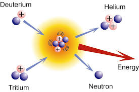 A LOT is at stake here: nuclear fusion, if the technical issues are overcome, could be a saviour for the human race at a time when energy resources are likely to be in short supply at a time when demand will be at an all-time high.
Man's ingenuity is such that even the technical challenges of fusion will be overcome when the imperative is great enough. I have faith in the ability of scientists and engineers (and even in politicians) to come up with the solutions in time to help produce a better world for my children and grandchildren. It's just a pity I shall not be around to see it.
Man's ingenuity is such that even the technical challenges of fusion will be overcome when the imperative is great enough. I have faith in the ability of scientists and engineers (and even in politicians) to come up with the solutions in time to help produce a better world for my children and grandchildren. It's just a pity I shall not be around to see it.
6m WSPR
For the last 36 hours I have been using WSPR on 6m to check for openings when busy with other things. I am surprised how often CN8LI (2171km) and I exchange spots even though I have only been running 500mW into the vertical V2000 antenna. I assume this is Es, but the path seems too consistently open for Es somehow.
I am disappointed more stations in the USA and Canada are not active on 6m WSPR: with a good number of stations both sides of "the pond" active, it would be an excellent way to spot those fleeting multi-hop Es openings at any time of the day or night.
I am disappointed more stations in the USA and Canada are not active on 6m WSPR: with a good number of stations both sides of "the pond" active, it would be an excellent way to spot those fleeting multi-hop Es openings at any time of the day or night.
Low cost, high performance 10GHz receiver
Using this set-up Ian can copy the 10GHz beacon GB3CAM at around 30km with just the LNB handheld in his front or back garden which is badly screened by tall trees! Using a small Sky dish, the signal is S9+60dB from a point just along the road.
Of course, with a small surplus satellite dish, a low cost TV USB dongle used as an SSB/CW RX at the LNB output frequency, this would make an excellent SDR for 10GHz with VERY low noise figure. The LNB quotes the NF as 0.1dB, which is remarkable.
With a small 10GHz FM or CW TX into a separate dish, a complete low cost 10GHz station is possible, probably for less than £50. I am sorely tempted to try this.
I have just seen Andy G4JNT's note about this http://www.g4jnt.com/PLL_LNB_Tests.pdf .
Earth-mode at 1kHz and 18kHz today
As a follow-up to my recent tests at 8.97kHz, today I repeated the QRSS3 earth-mode (through the ground) tests with my latest receiving equipment but this time at around 18kHz and 1.1kHz. TXing at 18kHz is legal as there is no appreciable radiation. As before, the TX was 5W into earth electrodes 20m apart back at home. I wanted to see how signal levels varied compared with 8.97kHz at my 3 usual test sites out to 6km distance from home.
Results were interesting: although signals were copied at 1.6km and 3.6km on both test frequencies, nothing at all was copied at 6km, where very good signals were copied on 8.97kHz a few weeks ago. Ground conductivity and weather conditions were identical on both test days: dry for the last several days, so conductivity likely to be lower than when the fen soil is saturated.
I have no real idea why 8.97kHz should appear to be a "sweet spot" in frequency. It is possible that other frequencies lower than 8.97kHz and higher than 1.1kHz may be even better. In all cases the RX loop was resonated and positioned on the ground varied for best signal.
 | |
| 1.12kHz earth-mode signal at 1.6km |
 |
| 17.952kHz earth-mode signal at 1.6km |
 |
| 1.12kHz earth-mode signal at 3.6km |
 |
| 17.952kHz earth-mode signal at 3.6km (note MSK signals close by) |
14 Jun 2013
Low costs SSB "Pixie" from Argentina
Pedro LU7HZ has sent me an update on work in Argentina on a low cost approach to an HF QRP SSB transceiver using very few parts. Basically they are using simple electronics coupled with an SDR approach to the modulation and demodulation process. My own approach would be the fully low tech approach (for a CW/DSB rig) but Pedro's approach is innovative and worth watching. I hope he produces kits or, at the least, documentation to allow others to duplicate the idea as it comes to fruition.
Roger,
This is a project we've been working together with Willoh (LW3DYL) which fits partially into your quest for an extremely low cost and easy to build rig ("UKP 20 decent HF...") although not using the low tech approach but the other way around.The design is still being debugged and more simplifications will be attempted (such as a more simpler TR/RX switch and eliminate the 7474 based quadrature filter replacing it by an RC approach. The net result should be a one IC and 4 transistors design plus PA final.The design uses an USB power source (out of an inexpensive cell phone switching power supply or straight out of the USB port at the PC) having 0.5W with it; more like 1W with +12V.Main software platform will be a modified version of KGKSDR. Main use should be CW or SSB although no reason why not to use it with PSK or FreeDV or WSPR.Should fit on a (small) pocket.Main limitation so far is available time from the builders to devote to the project.73 de Pedro LU7HZ
Dr. Pedro E. Colla
Va.Belgrano-Ciudad de Cordoba
Cordoba- Argentina"La vida no es esperar a que pase la tormenta, es aprender a bailar bajo la lluvia". Anonimo
Finningley optical transceiver progress
In the last couple of days, armed with my wife's close-up reading glasses, a magnifying glass, tweezers and a fine tipped soldering iron, I have been doing the SMA build of G4HJW's "Finningley" optical transceiver kit, designed to be used with 100mm optics (drain pipe and Poundland lenses!).
Bernie's instructions were first class with all the SMA parts for the receiver and the transmitter being organised sequentially with a clear layout diagram showing where each part has to be placed. It seems to have gone together very well with no snags, although I have still to add a few discrete parts including the LED and the PIN photodiode before testing can start. All being well, I should be able to start testing on Sunday as I am tied up with our church fete tomorrow.
 |
| The G4HJW designed optical transceiver |
11 Jun 2013
Efficient electrically short antennas
Way back in my early professional life I was responsible for the design and implementation of a tiny 70cm antenna that had to fit inside the Pye PF8 UHF handportable transceiver. The mechanical design team had left virtually no space for the plate antenna we had intended, so yours truly had to come up with a solution that both fitted and worked efficiently. I managed it by changing the plate antenna to a skeleton plate antenna. In the end it worked very well but the tuning was VERY sharp. Reference here should be made the Wheeler and the Chu limit that defines the bandwidth that an efficient electrically short antenna can achieve.
Basically the thing to remember is this: the smaller the antenna is the higher the Q, and the narrower the bandwidth is, for efficient operation. This is why magnetic loops can work well if designed with a very very high unloaded Q and why they have a very narrow bandwidth if working efficiently. It also explains why a short loaded antenna will have a narrower bandwidth if working efficiently. Dr Underhill has argued that a small magnetic loop actually violates the Chu limit.
There is a good analysis of small antennas at http://www.m0rzf.talktalk.net/RobCentral/E.S.Antenna.html which goes into some of the maths and looks at various electrically small antennas. Some are "snake oil" of course, but some well designed ones do work with the caveat of narrow bandwidth e.g. well designed magnetic loops.
What is the interest in all this for me today? Well, I am still thinking about HF operation at the new QTH and how to meet my goals of a small, low visual impact antenna, that works well. One thing in my favour is I tend to operate on quite small parts of the HF bands e.g. around the WSPR/PSK frequencies or around the QRP frequencies. As long as I am prepared to stay close to certain frequencies like 28.1246MHz I should be able to design a very small efficient antenna. I already know that a magentic loop antenna works very well indeed and would certainly meet my goals.
10 Jun 2013
Gardening at the new QTH


Incidentally I bought the turf out in the fens - much cheaper than the garden centre. It did involve driving my car into the middle of a large 100 acre field to collect it though (see RHS).
The Low Power SPRATbook.
 |
| http://www.rsgbshop.org/acatalog/ |
Perhaps I should also mention that my 14 component 80m CW transceiver is one of the articles. But don't let that put you off! The circuit works well and G3XIZ worked GM with his version (despite running only about 18mW) and was copied on Switzerland.
9 Jun 2013
PY1RO on 6m CW - real DX reception!
The magic band (6m) is full of surprises. I came into the shack this evening after gardening most of the day up at our new bungalow to hear some signals on 6m WSPR. Rather than decode, I tuned down to the DX portion of the band to hear PY1RO (GG87lb Brazil) coming through at 559 on CW on 50.108MHz at a distance of 9369km. I was copying him on the V2000 vertical and my FT817 with a long lossy feeder. A few minutes later and he had faded out completely! Although I called him a couple of times, I did not break the pile-up, not that I was really expecting to, HI. Still, it was good to hear my best DX on the band in some years. At this time of year the propagation is more likely to be multi-hop Es rather than TEP I believe. Here is a video of PY1RO on 6m (not this occasion though).
8 Jun 2013
G4HJW "Finningley" Optical Transceiver kit
 |
| The G4HJW optical transceiver kit |
Exactly when I'll get my kit built I'm not sure but it will be good to have one of these available for optical line-of-sight tests in the autumn. Once assembled, I shall be looking for some 2-way optical QSOs beyond the 10km speech contact I achieved with my own kit last summer. In East Anglia, the issue is finding some hills to allow long line-of-sight paths.
Bernie is, I understand, considering putting together a further batch of these kits, which make a good introduction to nanowave communications. In addition to these electrical kits, all that is needed is a microphone, headset and some simple optics than can be built for a few pounds.
See http://www.earf.co.uk/nanotrx.htm for more details
Yaesu price drop
 |
| http://www.universal-radio.com/ |
Playing with a ferrite rod at VLF
Just for amusement, but with a slight hope it might work, I tried resonating a LW ferrite rod coil (about 3.5mH) at 8.97kHz to see how it might perform as a miniature portable receiving loop in my earth-mode tests.
To test other antennas and VLF preamps, I first connect my 8.97kHz 5W transmitter into a resistive dummy load and check that I can detect the signal strongly some distance away locally (about 10m away only). The emissions from the cables are such that this gives me around 30-40dB S/N on Spectran with the usual settings on my 80cm loop. Switching over to the ferrite rod RX antenna it was hard to tell if a signal was there at all.
So, that's one experiment I'll close and report as a failure. Had it worked, even 10s of dB down, it might have made a magnetic field antenna that could have been deployed mobile. You may recall I tried /M on 8.97kHz a few months ago with my 80cm loop strapped behind the car, until someone pointed out this probably would have invalidated my car insurance and I stopped. I had vague ideas of dropping the VLF resonated ferrite rod close to the ground behind, somehow fixed from the rear bumper.
Ho hum, another idea bites the dust.
6 Jun 2013
Shortwave Radio Archive
Just spotted on the Southgate site that K4SWL is creating a website to archive shortwave broadcast recordings before these disappear. Already many SW BC stations have closed at least parts of their services. The HF broadcast bands are nothing like they were even 20 years ago. See http://shortwavearchive.com/ .
My shortwave radio experience started over 50 years ago listening to SW broadcast stations on a simple crystal set in my bedroom. As much as I hated the propaganda from the communist broadcasters like Radio Moscow and Radio Sofia, Bulgaria, I do miss them and their evocative interval signals.
See also https://sites.google.com/site/g3xbmqrp3/hf/interval and take a nostalgic trip down memory lane.
Good results with new VLF earth-mode RX system

The new preamp is just a single MPF102 impedance converter feeding into a small,low cost, external USB sound card (£3) that feeds my baby Asus X101CH netbook (£172) running Spectran software to display the received QRSS3 signal. The external soundcard was only needed as I didn't have a 4-pin jack to use the audio-in socket on the Asus.
Tests were carried out at the usual test sites at 1.6, 3.6 and 6km as well as one further (unsuccessful) test at 6.2km.


The next test will be to repeat this test at around 1kHz and possibly lower frequencies.I also want to try WSPR and repeat the tests at much higher LF frequencies around 72-73kHz. For the latter test, I need to build a simple down converter to audio.
5 Jun 2013
YouKits TJ2B SSB handheld kits on eBay
 The TJ2B 4-band SSB HF handheld is available direct from China for around £176 as a kit with all the SMA components already mounted on the PCBs. See eBay item number 271195721443.
Hamshop.cz
Although I have not used them myself (yet), www.hamshop.cz has a range of interesting and useful parts and kits available for purchase by PayPal. They ship worldwide too. Check out the page in English. As far as I can see, the prices are quite reasonable too.
Cloudbounce and scatter optical and IR tests
This morning I read a most interesting article about French cloudbounce and scatter optical tests using lasers. The article is some years old but makes a fascinating read. My own experience with clear air forward scatter at optical frequencies using relatively low powered red LEDs makes me believe that a LOT more is possible in this area. It is a bit like people saying, "UHF is only line-of-sight". Rubbish! With decent, easily built kit it is possible to copy QRP amateur signals over the horizon even at IR and visible optical frequencies.
See http://sd-1.archive-host.com/
See http://sd-1.archive-host.com/
First Icom IC7100 review on eHam.net
 |
| http://www.icomamerica.com |
6m WSPR and the transatlantic path by Es
 |
| 6m spots - note the drift |
Doppler on transatlantic 6m multi-hop Es signals might be a killer - I can imagine reflection points moving around in the E layer - but if not, then WSPR would be a great way to check for transatlantic openings.
I'll leave the 2W WSPR to the co-linear vertical running overnight tonight and on a few further nights through June and July. We just need LOTS more USA and Canadian stations both monitoring and RXing on 6m WSPR.
More VLF earth mode tests
Tomorrow morning, all being well, I hope to do a further test on VLF earth mode at 8.97kHz using my new Asus X101ch netbook using Spectran software and a simpler loop preamp on RX. Initially I'll test locally to check results are as expected before venturing further with the new (simpler and smaller) RX system.
Also, I want later to try TXing with a large, single turn, horizontal loop on the ground around the garden rather than the earth electrodes. On the basis that I am coupling into the ground and utilities, a horizontal loop might be as effective at coupling as the earth electrode antenna. A straight comparison of one against the other will be worth trying.
I also want to try WSPR at VLF using both my PCs.
4 Jun 2013
2m UKAC contest
 |
| The few stations worked this evening on 2m SSB |
3 Jun 2013
iPhone and iPod Touch

Of all the technology kit I have owned over the years, my iPod Touch 4g must rank as the very best. It gets used to surf the net over wi-fi, to communicate with our children and grandchildren when on holiday as well as for BBC iPlayer, music, videos, games, amateur radio applications and much more. Mine is the 8GB version but I see Amazon is now selling the 16GB 4th generation version for just £129, which is a bargain. I am sorely tempted to replace my aged unit.
For amateur radio apps that run on the iOS kit like iPhones and iPods, see http://www.g0hwc.com/iphone.html.
2 Jun 2013
4m/6m SSB/CW transceiver from Noble Radio
 |
| http://www.nobleradio.eu/files/NOBLE_RADIO_6N4_FRONTPANEL_BRANDED_small.jpg |
Does anyone know who Noble Radio is and in which country they are located? I have no idea about price or availability. Perhaps this is a "test the interest" concept model, rather like the Tokyo Hi-Power QRP radio of a few years ago. This was shown at a ham fair but never made it to market.
472kHz WSPR
After a few weeks break, I fired up the 472kHz kit this evening with about 5mW ERP (or less) from the 20m spaced earth electrodes in the ground. Not a lot of activity but exchanged WSPR reports with G7NKS (46km) and got a few reports from PA3ABK/2 (306km) and PA0RDT (243km). PA0A is always copyable when on WSPR as he rides above the local noise floor, unlike many others. Otherwise not a lot doing so far tonight. I guess everyone is watching football. I shall leave the kit running until later this evening to see what else appears.
One thing I MUST do is improve the 472kHz RX system as these days the noise pick-up on the earth electrode antenna is too great from local noise sources. For the new QTH I think I'll be installing a tuned RX loop and pre-amp at the far end of the garden as far from noise sources as possible. Even though directional, I suspect this will be better than the E-field probe, with the advantage that the loop may be rotated to null particularly bad noise sources locally.
1040z update: I shall leave the 472kHz running overnight but don't expect many more reports. These were the unique reports so far.

A new 23cm transverter kit from Australia
 |
| http://www.minikits.com.au/image/data/eme171_1200_files/eme23-trva.jpg |
I am very impressed when people release kits for 23cms and higher. Designing a kit that is easy to reproduce is not an easy task, although using SMA components and printed inductors/striplines makes the initial modelling easier and less subject to variations than when leaded parts are used.
Travel masts and SOTA accessories
I am wondering if SOTAbeams are intending to sell the YouKits TJ2B SSB handheld? This would be an ideal SOTA item.
FT817 replacement
Unless anyone has better data, there is still no news from Yaesu on the development of a replacement to the FT817. The most recent information I have is this (extract) from a posting on the FT817 Yahoo group 15 months ago by KE6ZGP. If development has started I would have expected some leaks by now. The FT817 remains a great QRP radio, but even a partial upgrade (adding internal ATU, speech processor, LiIon battery and maybe 4m) but keeping the same basic case/form factor would be welcomed. Such a kaizen development need not take that long.
"Not sure how many of you were watching the W5KUB Dayton stream this morning, but...
Tom interviewed the Yaesu rep about their new FT-DX3000 and the FT-1D, when all was said and done he started taking questions, I went ahead and asked about a possible replacement for the FT-817. The rep then stated - due to some parts (like the LCD screen) either being no longer available or extremely hard to find, they will likely replace the FT-817 in a couple years. He wasn't sure when exactly, R&D hasn't started onanything, but the earliest we can expect to hear any solid talk is two years from now.
Bryan Herbert - KE6ZGP"
Any better news anyone?
1 Jun 2013
No new solar maximum?
The latest summary for May 2013 on the Solar Terrestrial Activity Report at http://www.solen.info/solar/ shows that the (smoothed) international sunspot number (SIDC) reached 78.7 in May, some way below the last peak 96.7 back in Nov 2011. There is still a chance that another few months could raise the smoothed sunspot numbers above the Nov 2011 peak. Whatever, if these numbers remain at similar levels into the autumn we will have decent conditions on the higher HF bands.
 |
| http://www.solen.info/solar/images/solar.png |
Back in action after 2 weeks out
Well, the Swiss train holiday is over, the grandchildren have gone home to mums and dads after a week with us, and we have our house back. For the last week I forgot we had carpets on the floor as they were strewn with toys. We love our grandchildren so much - they really are what life is all about - but the house was more like a war zone during their stay! The youngest staying with us was just 2 and the eldest 5. You get the picture.
Now that we are back to normal, amateur radio experiments can resume. I'll probably resume 472kHz and 28MHz WSPR tomorrow and hope to do some further VLF earth mode tests during the week. I may also enter the 2m UKAC contest on Tuesday evening.
Now that we are back to normal, amateur radio experiments can resume. I'll probably resume 472kHz and 28MHz WSPR tomorrow and hope to do some further VLF earth mode tests during the week. I may also enter the 2m UKAC contest on Tuesday evening.
Subscribe to:
Posts (Atom)


